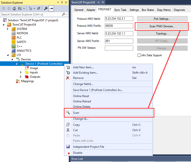
Appending via the Scan function
The first and recommended option is to use Scan PNIO Devices. This feature is comparable with the "ScanBoxes" feature which, however, is available only in CONFIG mode. After successful scanning, if PROFINET devices were found a dialog opens in which settings and configuration can be made on the devices and devices with module configuration can be added.
The prerequisite for finding PROFITNET devices on the bus is that they are present and switched on and that the GSDML file of the respective devices is located in the path C:\TwinCAT\3.1\Config\Io\Profinet.
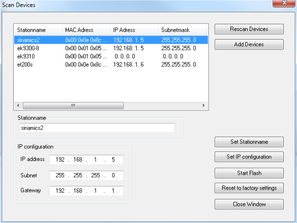
Various settings or project planning can be carried out for the devices here. These are adopted only when the corresponding button is explicitly pressed. When setting the name, care must be taken that only PROFINET-compliant characters are used. This also applies to the IP address; only valid combinations of IP and subnet are to be used. Name and IP are checked for correctness when setting PROFINET devices. If this is not the case, DCP_SET is acknowledged with an error. By pressing the Rescan button, any changes that were made can be read back. In addition the selected device can be signaled. This functionality is PROFINET-specific. The signaling is vendor-specific. As standard, however, the signal must arrive with a frequency of 2 Hz. For example, the Beckhoff BK9103 Bus Coupler signals itself by the alternate flashing of two LEDs at a rate of 2 Hz. This function is very helpful for identifying the devices in this list. The flashing is stopped again by pressing the button once more. The flashing is stopped by closing the ScanDevices window. Subsequently, one or more devices can be marked with the Ctrl button. The selected devices are adopted into the project by pressing Add Devices
Upon pressing Add Devices, the following question box opens:
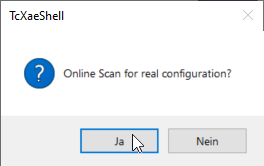
Yes button:
An attempt is initially made to determine the ModuleIdentNumber of the DAP (Device Access Point) by an implicit read access. If this fails a corresponding dialog opens containing the possible DAPs, which must then be selected manually. If all boxes have been appended, a ‘Reload Devices’ automatically takes place, i.e. the devices (adaptors) created are transmitted to the PROFINET driver. Subsequently, a distinction is made as to whether the box is a normal device or a drive with Profidrive support. For a normal device the actual module population (RealIdentificationData) is read out again via an implicit read access. If it is a Profidrive device, conversely, the required information is read out by a Profidrive access. A Supervisor AR is established for this purpose. The required write accesses can take place within this. The Submodule interface on the DAP is taken here as the Parameter Access Point. The parameter access takes place via data record 47, much like the case of the Profibus beforehand. When using Sinamics, however, it must be noted that such an access is only permitted from version 4.3 SP2. If an older version is used, a corresponding error message appears and the parameterization must take place manually.
Once the automatic module parameterization has been completed, a question box appears asking whether the port data should be read in automatically. Here again, the port connection for the individual devices is read out via an implicit read access. The real port connection must be known for the various services. This can be limited to diagnostic services, although automatic device startup also requires this option (via alias), or specification of IRT planning. If this dialog is acknowledged with "no" or if the read access has failed, such a connection can also be made manually at the individual ports in the TwinCAT project.
If the port connection has been successfully generated, a query also appears in the case of an IRT Controller (e.g. project planning on an EL6632) asking whether all devices are to be automatically connected in IRT Mode (provided they support it). If this is affirmed the cable length is additionally set to 10 m copper cable on all projected ports. The IRT algorithm requires this information for the calculation of the signal propagation delays. The precise cable length is not so important here (approx. +/-10 m), because the runtime delays tend to be small at 100 Mbit/s (5 ns/m). If the automatic switchover is not to take place immediately, these points can also be modified later either on the protocol or on the individual devices (on the interface or port submodule).
No button:
For each device a check is performed to see if the GSDML exists in the appropriate folder (..\\TwinCAT\3.1\Config\Io\Profinet). If this is the case, the list of possible DAPs is read in. Subsequently a selection dialog is opened so that the corresponding DAP can be selected. Once the devices have been appended in the project, the API below the Box can be accessed and the modules and submodules can be manually appended via it.