Configuring Alarms and Conditions
In order to configure Alarms and Conditions (A&C) you must first set up the Condition Controllers. These are container units that group together alarms.
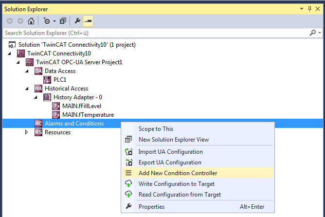
Condition Controllers are added to the configuration using the context menu command Add New Condition Controller.
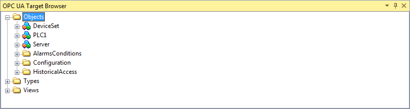
Once you have created a Condition Controller, add the desired variables to the controller and monitor them in terms of alarms and conditions. A Condition is created for each variable, which specifies the parameters for monitoring. These variables must already exist on the selected OPC UA Server when the engineering is implemented. You can use the integrated OPC UA Target Browser to select the variables and then add the variables from the Target Browser to the Condition Controller by drag and drop.
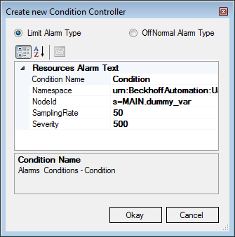
In the dialog box which then opens you can define the Condition type and further parameters for the monitoring, e.g. SamplingRate and Severity.
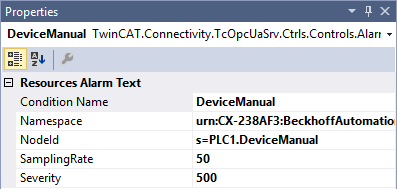
Depending on the Condition type selected, specify additional parameters in the Condition properties window. The threshold values for the respective Condition type are displayed as individual entries in the tree view of the configuration. Here too, you can configure the corresponding parameters in the properties window.
Subsequently you have to define the alarm texts that are to be sent to the OPC UA Client when a Condition is triggered. How to create alarm texts is described in the chapter Configuring alarm texts. You can drag and drop the alarm texts onto the respective threshold value of a Condition.
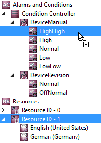
Alarm type OffNormal
An OffNormal alarm type is used to define which state of a Boolean variable is evaluated as normal. An alarm is triggered if the variable value deviates from this. The PLC must be used for working with value ranges (e.g., integer or double variables). Depending on the value, a corresponding TRUE or FALSE state is then passed to the OPC UA Server.
State | Value range |
|---|---|
Normal | TRUE or FALSE, depending on the user's decision. |
OffNormal | TRUE or FALSE, depending on the configuration of the normal state. Cannot be configured by the user. |
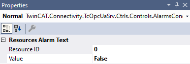
The first step is to configure the normal state as described above. The user then defines an alarm text for the respective state (OffNormal and Normal) via Resources. This can be done either by drag and drop or by selecting from the Resource ID drop-down list.
Alarm type limit
With an alarm type limit you define different threshold values upon whose reaching an alarm is to be sent. The following table describes the different threshold values using an example configuration.
State | Example threshold values | Associated value range (INT) |
|---|---|---|
HighHigh | 5000 | 5000-32767 |
High | 2000 | 2000-4999 |
Normal | - | 1000-1999 |
Low | 1000 | 500-999 |
LowLow | 500 | -32768-499 |
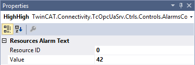
In the first step, the various threshold values are configured as described above. The user then defines an alarm text for the respective state (HighHigh, High, Normal, Low, LowLow) via Resources. This can be done either by drag and drop or by selecting from the Resource ID drop-down list.
Requirements
Products | Setup versions | Target platform |
|---|---|---|
TF6100 | 4.x.x | IPC or CX (x86, x64, Arm®) |
See also: Connecting to a server