Electric/hydraulic hybrid axes
Hybrid axis concepts
The manufacturers of hydraulic components have developed a number of solutions for the design of such an axis. In order not to have to create a dedicated solution for each model of each manufacturer, generalized concepts were developed that combine a group of comparable models. The trailing letters (a, b, c, ...) denote equivalent variants of a concept. In the following section, these concepts and variants are presented using samples. The list of these samples is, by its very nature, incomplete.
 | The screen contents shown below are only visible if the 'hybrid' flag is set on the Valve tab. |
Simplified representation
The concepts listed below require the use of various pressure limiters and anti-cavitation check valves for their safe and long-term function. These components are indispensable but have no direct influence on the basic function of the axis. For a better understanding, all circuits are simplified to a greater or lesser degree and should not be regarded as documentation of an actual product.
1: Simulation of a synchronous cylinder without regenerative circuit
The control behavior of a synchronous cylinder is simulated using a hydraulic synchronous or differential cylinder and an adapted pump arrangement. A gear shift can be realized by a pump changeover, although this results in a different concept.
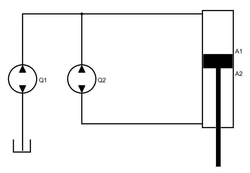
1a: Simulation of a synchronous cylinder with a differential cylinder
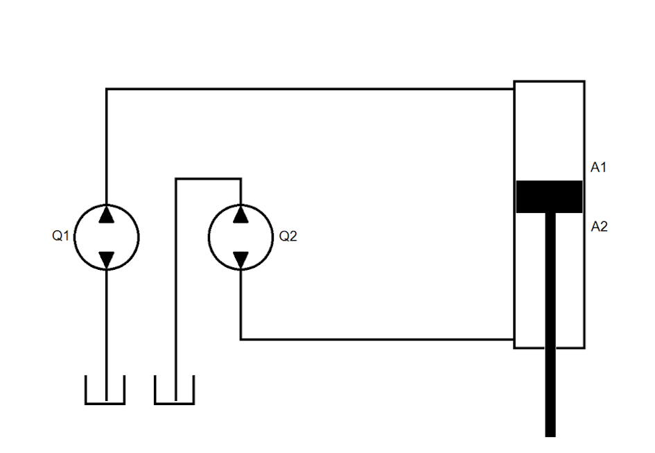
Manufacturer / Product: Voith Turbo / CLDP.
Here, two pumps with flow rates adapted to the cylinder areas are operated on a motor shaft. The flow rates of the pumps Q1 / Q2 must be adapted to the ratio of the effective areas. Since this is not always perfectly possible, complex pressure distributions can result, depending on the situation.
The control results in the behavior of a synchronous cylinder with direction-independent feed constant.
Hydraulically a differential cylinder is present and an exchange volume is to be stored.
No gear shift is available. It can be realized by synchronous flow-switchable pumps. This results in a different concept.
Required parameters: Effective area in positive direction (1), effective area in negative direction (2), volume per revolution at the effective area in positive direction (3), maximum pump speed (4).
Automatically calculated parameters: Volume per revolution at the effective area in negative direction. The ratio of the effective areas is used.
Automatically set parameters: The selectable areas are 0, the rotation volumes for force mode are equal to the values for rapid mode.
1b: Simulated synchronous cylinder with multiple differential cylinders
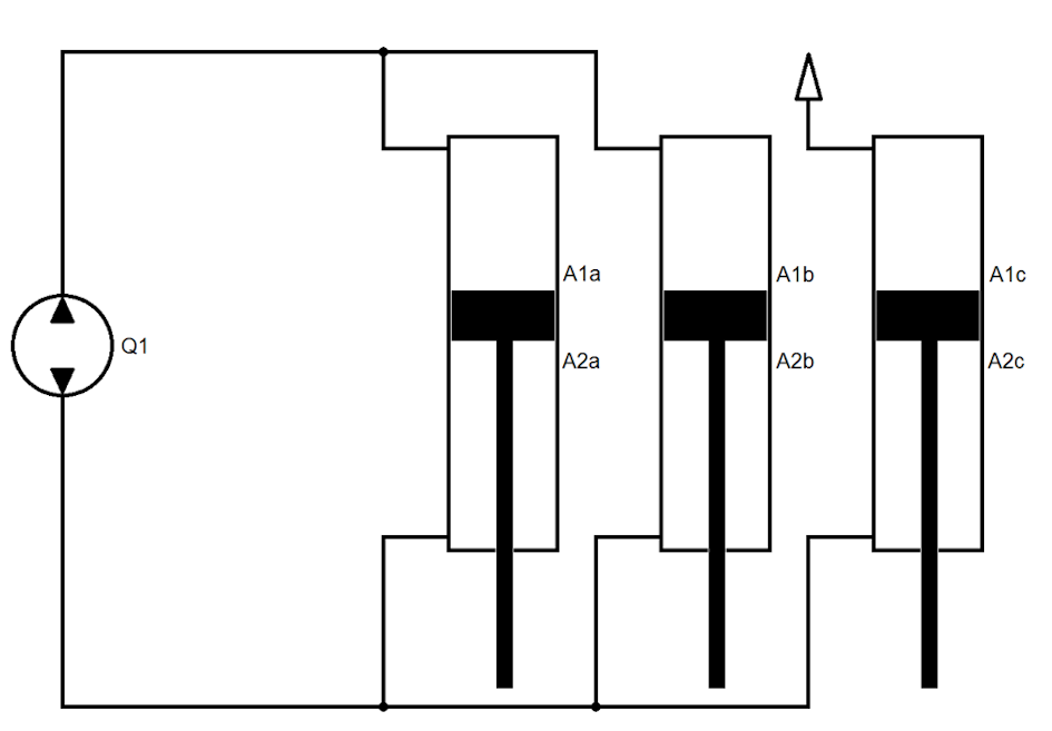
Manufacturer / Product: Bucher / Demo HMI2018.
Here, three differential cylinders with an area ratio of 2:3 are mechanically connected in parallel. The three smaller areas A2abc are hydraulically connected in parallel and form an effective area. Of the larger areas, A1ab are hydraulically connected in parallel, while the third area A1c is ventilated.
For control purposes, the result is a compound synchronous cylinder with direction-independent feed constant.
Hydraulically a synchronous cylinder is present and no exchange volume is to be stored.
According to the manufacturer a gear shift is possible. This results in a different concept.
Required parameters: Effective area in positive direction (1), effective area in negative direction (2), volume per revolution at the effective area in positive direction (3), maximum pump speed (4).
Automatically calculated parameters: Volume per revolution at the effective area in negative direction. The ratio of the effective areas is used (in this case 1:1).
Automatically set parameters: The selectable areas are 0, the rotation volumes for force mode are equal to the values for rapid mode.
2: Simulation of a synchronous cylinder with regenerative circuit
The control behavior of a synchronous cylinder is simulated using a hydraulic differential cylinder and an adapted pump arrangement in a regenerative circuit. A gear shift can be realized by a pump changeover, although this results in a different concept.
2a: Simulation of a synchronous cylinder with regenerative circuit
Manufacturer / Product: Bosch Rexroth / application.
Here, two pumps with flow rates adapted to the cylinder areas are operated on a motor shaft. The flow rates of pumps Q1 / Q2 must be adapted to the area ratio of rod cross-section / ring area. Since this is not always perfectly possible, complex pressure distributions can result, depending on the situation.
The control results in the behavior of a synchronous cylinder with direction-independent feed constant.
Hydraulically a differential cylinder is present and an exchange volume is to be stored.
No gear shift is available. It can be realized by synchronous flow-switchable pumps. This results in a different concept.
| The oil volume in Q1 and the volume of lines through which only their flow rate flows must be smaller than the oil exchanged during operation for the cross-section of the piston rod. Otherwise there is no safe oil exchange. |
Required parameters: Effective area in positive direction (1), effective area in negative direction (2), volume per revolution at the effective area in positive direction (3), maximum pump speed (4), maximum pump speed (5).
Automatically calculated parameters: Volume per revolution at the effective area in negative direction. The ratio of the effective areas is used.
Automatically set parameters: The selectable areas are 0, the rotation volumes for force mode are equal to the values for rapid mode. The flag for regenerative operation is set.
3: Gear shift through switching of effective areas
Switching valves are used to make the effective areas of a cylinder effective or ineffective or to connect them in a variable manner. In some cases, 'virtual' areas are created which have to be taken into account in the oil quantity but do not contribute to force build-up.
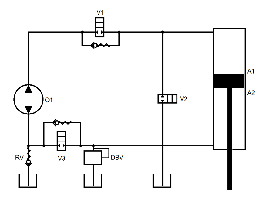
3a: Use of a cylinder with 2+1 active areas
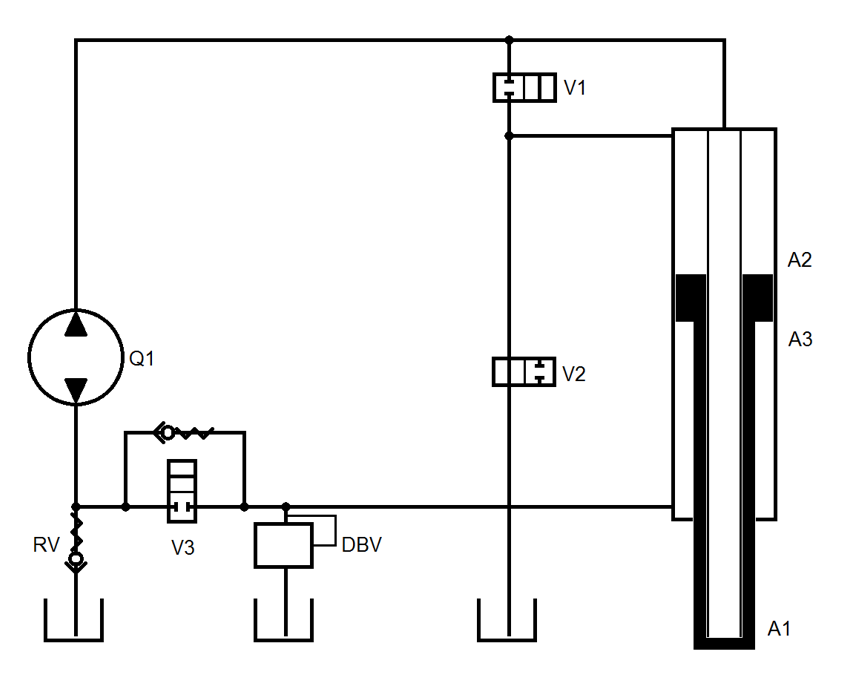
Manufacturer / Product: EH-D.
Rapid traverse switching: V1 and V2 (note valve symbol!) are switched off. V3 must be switched to extend the cylinder. If A1 and A3 are the same, no oil is exchanged with the reservoir. Otherwise, differential oil must be taken in via the RV or displaced via the DBV, depending on the direction.
Force mode: V1 and V2 (note valve symbol!) are switched on. During extending, activation of V3 is mandatory. The oil quantity from A3 is supplemented for A1/A2 via the RV. Retracting is only possible in this configuration by displacing a considerable volume via the DBV. Heat is generated during this process. This combination of valve switching and direction of rotation of the pump is useful for pressure reduction, but it should not be used for active movement.
Required parameters: Active area in extending direction = A1 (1), added active area in extending direction = A2 (2), active area in retraction direction = A3 (3), added active area in retraction direction = 0 (4), volume per revolution at active area in positive direction (5), maximum pump speed (6).
Automatically calculated parameters: The volume per revolution on the active area in negative direction is set equal to the volume per revolution on the effective area in positive direction.
Automatically set parameters: The rotation volumes for force mode are equal to the values for rapid mode.
3b: Virtual area switching generation
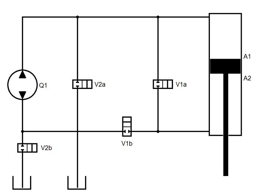
Manufacturer / Product: Voith Turbo / CLSP.
In this case, the valves produce a gear shift.
Rapid mode:
During extending, V1a and V2b are activated. The oil quantity for the ring area is exchanged via V1a between the areas. The oil quantity for the rod cross-section is supplemented via V2b by the pump from the reservoir. Depending on the circuit, the rod cross-section is hydraulically supported. The cylinder has a low natural frequency and should be operated with adapted dynamics.
During retracting, V1b and V2a are activated. The oil quantity for the ring area is exchanged via V1b by the pump between the areas. The oil quantity for the rod cross-section is diverted to the reservoir via V2a. Due to the circuit, area A2 is only subjected to the pre-load pressure of the reservoir. The cylinder is only to some extent able to brake by its own force. It should be operated with adapted dynamics.
Force mode:
During extending, V1b and V2b are activated. The oil quantity for the ring area is exchanged via V1b by the pump between the areas. The oil quantity for the rod cross-section is supplemented via V2b by the pump from the reservoir. Due to the circuit, area A2 is only subjected to the pre-load pressure of the reservoir. The cylinder is only to some extent able to brake by its own force. It should be supported and slowed down by the process.
During retracting, V1b and V2b are activated. The oil quantity for the ring area is exchanged via V1b by the pump between the areas. The oil quantity for the rod cross-section is discharged via V2b through the pump to the reservoir. Due to the circuit, area A2 is only subjected to the pre-load pressure of the reservoir. The cylinder is only to some extent able to move by its own force. It must be checked whether it is able to overcome the forces generated by gravity and friction. This circuit should only be used to reduce forces generated in extending direction.
Required parameters: Effective area in extending direction = rod cross-section (1), added effective area in extending direction = ring area (2), effective area in retraction direction = ring area (3), added effective area in retraction direction = 0 (4), volume per revolution at effective area in positive direction (5), maximum pump speed (6).
Automatically calculated parameters: The volume per revolution on the effective area in negative direction is set equal to the volume per revolution on the effective area in positive direction.
Automatically set parameters: The rotation volumes for force mode are equal to the values for rapid mode.
3c: Virtual area switching generation
Manufacturer / Product: EH-D / 18-0129-001-HY-K.
In this case, the valves produce a gear shift.
Rapid mode:
During extending, activation of V1 is optional, activation of V2 and V3 is mandatory. The oil quantity for the ring area is exchanged via V3 / V1 between the areas. The oil quantity for the rod cross-section is added via V2 from the reservoir. Due to the circuit, area A1 is only subjected to the pre-load pressure of the reservoir. Due to the circuit, area A2 is only subjected to the pre-load pressure of the reservoir. The cylinder is only to some extent able to move by its own force. It must be checked whether it is able to overcome the forces generated by gravity and friction. This circuit should only be used to reduce forces generated in extending direction.
During retracting, activation of V1 and V2 is mandatory, activation of V3 is optional. The oil quantity for the ring area is exchanged via V1 / V3 by the pump between the areas. The oil quantity for the rod cross-section is diverted to the reservoir via V2. Due to the circuit, area A2 is only subjected to the pre-load pressure of the reservoir. The cylinder is only to some extent able to brake by its own force. It should be operated with adapted dynamics.
Force mode:
During extending, activation of V1 is optional, activation of V3 is mandatory, activation of V2 is prohibited. The oil quantity for the ring area is exchanged via V3 / V1 by the pump between the areas. The oil quantity for the rod cross-section is supplemented via RV by the pump from the reservoir. Due to the circuit, area A2 is only subjected to the pre-load pressure of the reservoir. The cylinder is only to some extent able to brake by its own force. It should be supported and slowed down by the process.
During retracting, activation of V1 is mandatory, activation of V3 is optional, activation of V2 is prohibited. The oil quantity for the ring area is exchanged via V1 / V3 by the pump between the areas. The oil quantity for the rod cross-section is diverted to the reservoir via DBV. Due to the circuit, area A2 is only subjected to the limiting pressure of the DBV. The cylinder is only to some extent able to move by its own force. It must be checked whether it is able to overcome the forces generated by gravity and friction.
Required parameters: Effective area in retraction and extension direction = ring area (1, 3), added effective area in retraction and extension direction = rod cross-section (2, 4), volume per revolution at the effective area in positive direction (5). The added effective area in the extension direction must be marked as 'virtual' (7), since it must be taken into account when calculating the required speed, but does not contribute to the force build-up, maximum pump speed (6).
Automatically calculated parameters: The volume per revolution on the effective area in negative direction is set equal to the volume per revolution on the effective area in positive direction.
Automatically set parameters: The rotation volumes for force mode are equal to the values for rapid mode.
3d: Virtual area switching generation
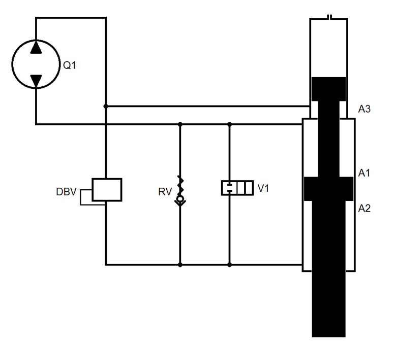
Manufacturer / Product: Voith Turbo / PDSC.
In this case, the valves produce a gear shift.
Rapid mode:
During extending and retracting, activation of V1 is mandatory. Part of the oil quantity from A2 is used regeneratively for A1, the remaining quantity is exchanged via pump with A3. Since A3=A1-A2, the behavior is synchronous, both hydraulically and from a control perspective.
Force mode:
During extending, activation of V1 is prohibited. Since the pressure in A1 is higher than the pressures in A2 and A3 due to the effect of the pump, the RV locks and the DBV connects A2 and A3. Since A1=A2+A3, the behavior is synchronous, both hydraulically and from a control perspective.
Retraction in force mode is not possible since the RV generates the rapid mode configuration with hydraulic control.
Required parameters: Effective area in retraction and extension direction = A3 (1, 3), added effective area in retraction and extension direction = A2 (2, 4), volume per revolution at A1 (5), maximum pump speed (6).
Automatically calculated parameters: The volume per revolution at A2+A3 is set equal to the volume per revolution at the effective area in positive direction.
Automatically set parameters: The rotation volumes for force mode are equal to the values for rapid mode.
3e: Virtual area switching generation
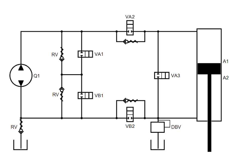
Manufacturer / Product: EH-D / ECO.
In this case, the valves produce a gear shift.
Rapid mode:
During retracting, activation of VA1 and VA2 is mandatory, activation of VB2 is optional. Activation of VB1 and VA3 is prohibited. The pump conveys oil from A1 to A2; the portion originating from A2 for the rod cross-section is discharged via VA1 to the reservoir.
During extending, activation of VA1 and VB2 is prohibited. Activation of VB1 and VA2 is optional. Activation of VA3 is mandatory. The oil quantity from A2 is used regeneratively via VA3 for A1, the remaining quantity is added via pump and VB1 from the reservoir.
Force mode:
During extending, activation of VA1 and VA3 is prohibited. Activation of VB1 and VA2 is optional. Activation of VA2 is mandatory. The oil quantity from A2 is used regeneratively via VB2 for A1, the remaining quantity is added via pump and VB1 from the reservoir.
Retracting in force mode is not possible because the DBV would have to discharge the oil quantity for the rod cross-section at high pressure.
For decompression of area A1, the pressure can be reduced in force mode, while activation of VB1 and VA2 is mandatory.
Required parameters: Effective area in retraction direction = ring area (1), added effective area in retraction direction = 0 (2), effective area in extension direction = rod cross-section (3), added effective area in extension direction = ring area (4), volume per revolution at A1 (5), maximum pump speed (6).
Automatically calculated parameters: The volume per revolution at A2 is set equal to the volume per revolution at the effective area in positive direction.
Automatically set parameters: The rotation volumes for force mode are equal to the values for rapid mode.