Link an axis object to hardware
Automatic creation and linking of an axis when scanning the EtherCAT configuration
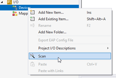
- 1. Scan the EtherCAT fieldbus configuration: I/O Nodes > Devices > Context menu (right-click) > Scan
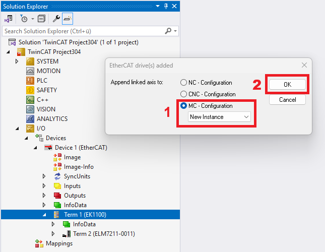
- 2. In the “EtherCAT drives added” dialog box that opens, select the MC – Configuration (1) option. If a motion configuration has already been created in the TwinCAT project, you can select the desired instance from the drop-down menu. Selecting New Instance creates a new motion configuration node. Confirm the dialog with OK (2).
- In the TwinCAT project in Solution Explorer, a new motion configuration and an axis are created. It is automatically linked to the hardware.
Link to I/O – Manually link an axis
Procedure – Example for EL72xx/ELM72xx, AX5000, AX8000
- The hardware configuration has been created.
- A motion configuration with one MC3 axis has been created.
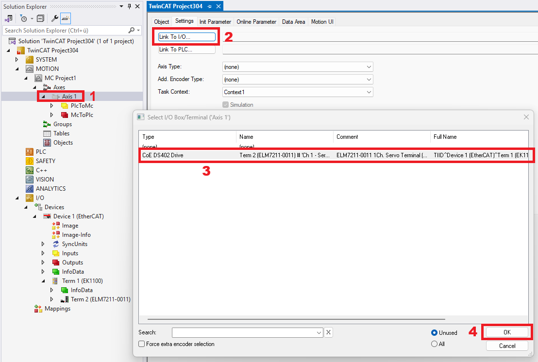
- 3. Select the axis you want to link (1) > Settings tab.
- 4. Click on Link to I/O...(2).
- 5. Select the drive hardware (3) you want to link.
- 6. Confirm your selection with OK (4).
Procedure – Example: Analog drive with an additional encoder
- In this case, the same steps as in the previous section apply initially. In the “Select I/O Box/Terminal” dialog box, note the following selection:
- 7. Select the Force extra encoder selection option before clicking OK to close the dialog box.
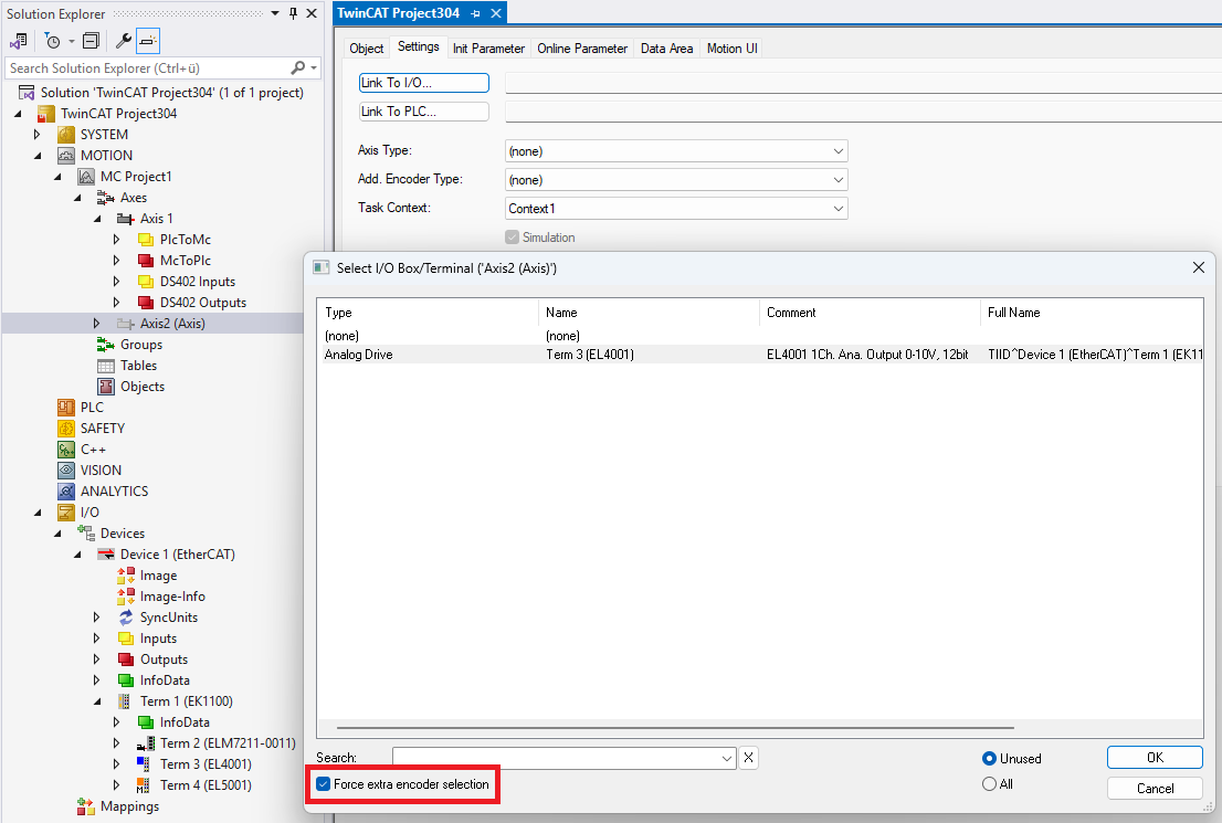
- Another dialog opens.
- Select an encoder and confirm your selection by clicking the OK button.
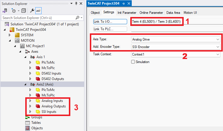
- The text field next to the Link to I/O… button displays the linked hardware devices (1).
- The type of axis and the additional encoder are displayed (2).
- The cyclic interfaces between the MC3 axis and the I/O devices are visible (3).