Axes
The Axes section displays an overview of all axes in the MC project. You can use this to enable axes and jog them.
If the project also includes movers, you can view an overview of all movers on the “Mover” tab. Further information on this topic can be found in the XPlanar documentation.
It is also possible to link the axis objects directly to the PLC and the hardware (I/O) on this page. Alternatively, you can link each axis under the Settings tab.

Using the Axes UI
To enable or move axes from this view, select the desired axes. You can then control and operate the axes using the Sidebar.
You can minimize or collapse the Sidebar using the arrow in the upper-left corner and expand it to its normal size again.
Load Links
The Load Links button retrieves the current I/O and PLC links and displays them in the table.
If an object is linked, the green  icon appears.
Link I/O and Link PLC – Linking Manager
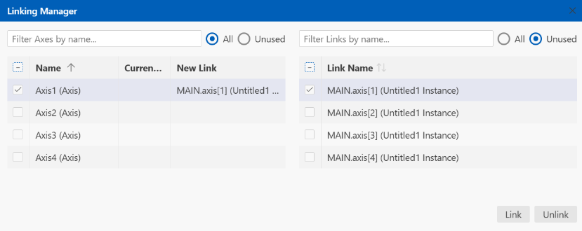
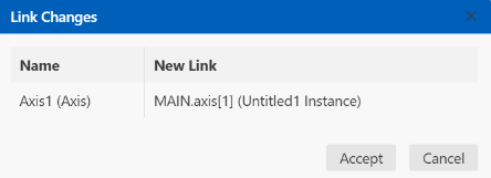
Clicking on Link I/O or Link PLC opens the Link Manager. Using Link PLC, you can link axis objects to AXIS_REF instances in the PLC or unlink them again. Link I/O can be used to link axis objects to hardware components. The axes are linked in the order in which they are selected.
Example: In the system configuration (left table), select Axis2, Axis4, and Axis3. In the PLC configuration (right table), select MAIN.axis[4], MAIN.axis[2], and MAIN.axis[3]. This results in the following links: Axis2 + MAIN.axis[4], Axis4 + MAIN.axis[2], and Axis3 + MAIN.axis[3].
Settings
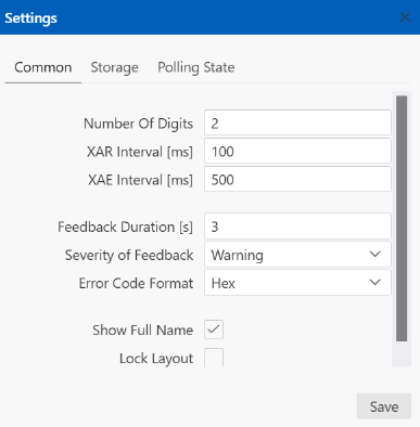
Under “Settings”, you can configure various settings for the Motion UI. Clicking Save saves the settings you have configured within the project.
Common
Selection | Description |
|---|---|
Number Of Digits | Number of decimal places to display. |
XAR Interval [ms] | Specifies the interval at which data is read from the runtime environment. |
XAE Interval [ms] | Specifies the interval at which data is read from the engineering environment. |
Feedback Duration [s] | Sets the duration for which the feedback window (pop-up) is displayed. |
Severity of Feedback | Specifies from which level events are displayed in the feedback window. |
Error Code Format | Options: Hex, Decimal Specifies the format in which the error code is displayed (as a hexadecimal or decimal number). |
Show Full Name | If necessary, enlarges the axis name display so that it is shown in its entirety. |
Lock Layout | If selected, this prevents cards from being accidentally moved or resized. Everything continues to work as usual, only the layout is fixed. |
Storage unit
Selection | Description |
|---|---|
Layouts and Inputs | Clicking Clear resets the layout to the default view and clears any entries made in the UI. |
Settings | Clicking Clear clears the settings you have configured for this interface. |
Notice | |
Clearing cannot be undone Export any layout you want to keep from the Layout Manager before clearing storage. Clearing cannot be undone. |
Polling State
The polling state displays data from the UI's last request to the Motion driver for diagnostic purposes.
Selection | Description |
|---|---|
Polling State | Idle / Polling / No Connection / Error |
Error message | Error message that appears if an error occurs in the communication between Motion UI and the driver. |
Last Fetch Duration | Total duration of the UI's most recent request to the motion driver. |
Last Bundled Response | Final response from the driver to the UI. |
Zoom In/Out
You can zoom in and out by holding down the [CTRL] key on your keyboard and scrolling the mouse wheel at the same time.