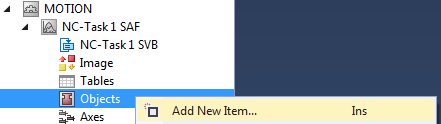
Configuring a Node Connector
Configuring for MC_SetCoordinateTransform is illustrated at the example of a pallet located relative to the WCS or MCS coordinate system.
 | Node connector objects Node connector objects are used by MC_SetCoordinateTransform and MC_TrackConveyorBelt. Instead of coordinate frames, node connector objects are addressed by the PLC as representatives. |
Example
To introduce a coordinate transform using MC_SetCoordinateTransform:
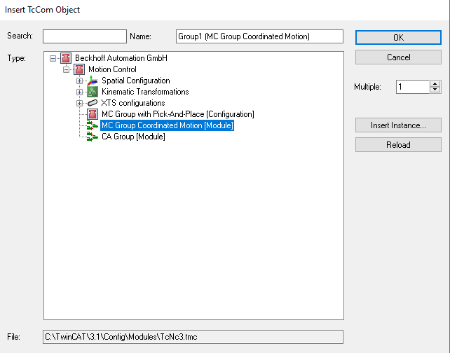
- 1. Insert an
MCGroup.
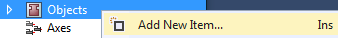
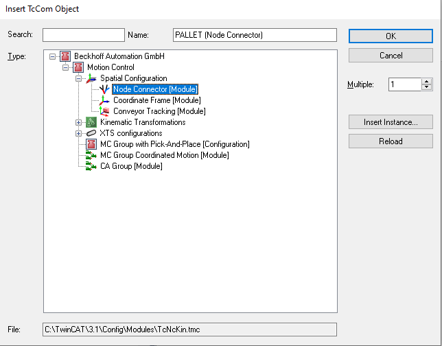
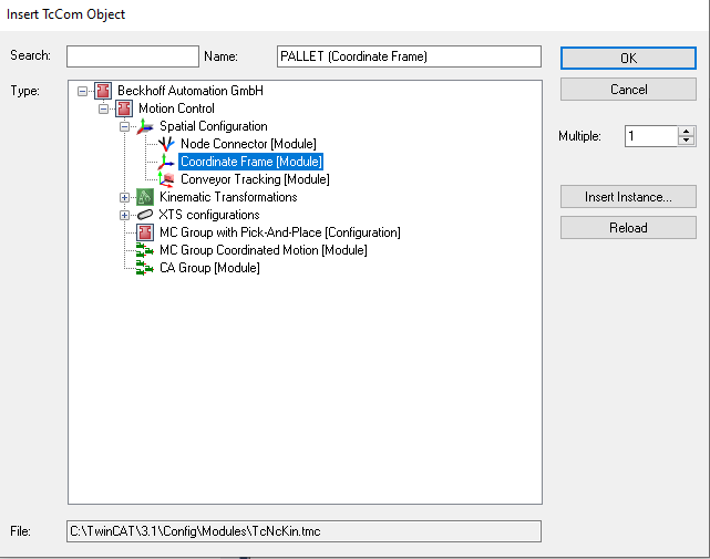
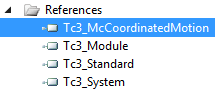
- 2. Insert a Node Connector.
- 3. Insert a Coordinate Frame.
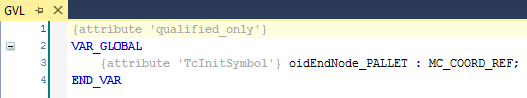
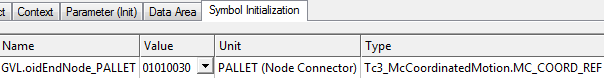
- 4. Enter relevant Node Connector Parameters - in this example the end node refers to the pallet object identification.
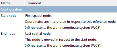
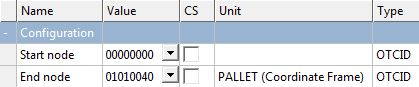
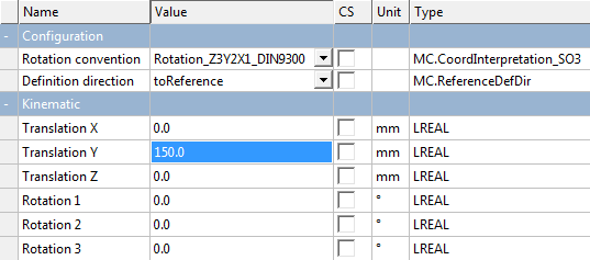
- 5. Enter relevant Coordinate Frame Parameters.
- 6. Link the inserted Node Connector to the
PLC.


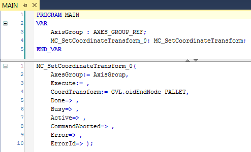
- Finally‚ you can insert the
MC_SetCoordinateTransformfunction block.
| The axis group AxisGroup is linked with the Pick-and-Place function blocks. |
| For axis movements a move command has to be programmed, e.g. MovePath. |