Geo Compensation
Geometrical Information
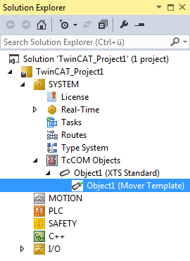
Geometrical information is required for geo-compensation. This geometrical information is configured in the TwinCAT SYSTEM\TcCOM Objects subtree.
Table of an XTS standard object
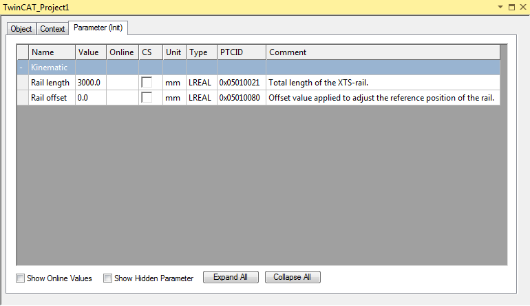
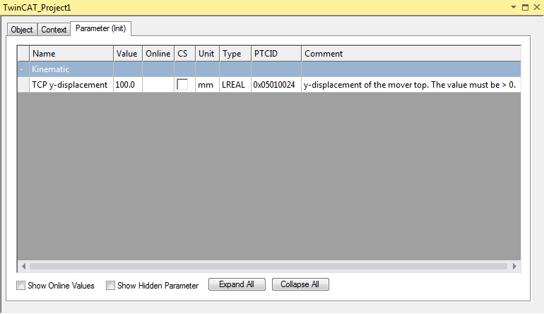
Table of a mover template object
The XTS Standard Object describes the geometry of a standard XTS motor path. Objects designated as mover templates each define the geometry of a single mover type, including a shift along the y-shift component. A Mover Template is added to the XTS Standard Object to extend the standard geometrical information with the geometrical information of the mover. A Mover Template can be referred to by all axes that use its configuration.
XTS Standard Object
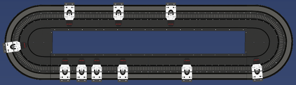
The XTS Standard Object defines a motor path that has the starter kit geometry including two curves of 180 degrees. These curves are connected by two straight sections of equal length. The length of these straight sections can be changed during configuration. Thus, the Rail Length parameter of the XTS Standard Object configures the total length: both curves plus both straights. A zero shift (offset) can be configured in the XTS Standard Object for the position information on the XTS motor path x.
Rail length: Total length of the XTS rail.
Rail offset: Offset value for adjusting the reference position of the rail. See below and the figure Starter kit geometry.
Rail Offset: A zero shift
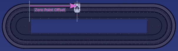
Each XTS system includes a segment that sets the zero position in the x-direction. The geo-compensation uses the starter kit geometry. In the geo-compensation, the segment for determining the zero position has a fixed place. It is the curved element in the upper left corner before the first straight element.
To set the zero position elsewhere and to start counting the x-coordinate from another position, a zero shift – the Rail Offset – can be defined.
The figure shows the Rail Offset between the two dashed lines. The left line shows where the segment for setting the zero position ends. The dashed line on the right and the mover shown illustrate how a position value is interpreted by a mover. The dashed line divides the mover into two halves. The mover is at the zero position. However, the determination of a Rail Offset itself does not require a mover.
 | Note on the availability of the zero shift Currently, the starter kit geometry is the only geometry available for geo-compensation: Two curves of 180 degrees and two straight sections of equal length that connect these curves. |
Mover Template Object
A Mover Template Object initially adopts the geometrical information of the XTS Standard Object. In addition, it describes a mover path geometry, i.e. the y-shift of a particular mover type. A Mover Template can be reused for different movers that have the same path geometry, i.e. the same tool center path. A Mover Template can be activated and deactivated in run mode. The template for a mover can thus be changed in run mode.
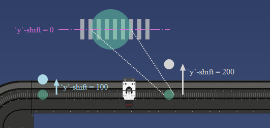
y-shift of the TCP: Configurable y-shift for controlling the path dynamics. The y-shift must be positive or equal to zero. For each point of an XTS motor path, it describes a point of a mover path that lies perpendicular to the tangent of the motor path that runs through this point of the motor path. In this direction, with orientation of the geometry of the XTS Standard Object to the outside, this point of the mover path is shifted away from the XTS motor path by the value of the y-shift. This shifted point is also known as the tool center point (TCP). Together, the y-points describe a path that is termed the tool center path.
On a straight section, the motor coils form a pattern similar to a zebra crossing. If this straight section lies in the middle of this pattern and divides each motor coil into an upper and a lower half, the y-shift has a value of zero on this straight section (see figure). If the y-shift is zero, the path dynamics are controlled collectively in the vertical center of the motor coils.
| Note on the availability of the zero shift Currently, the starter kit geometry is the only geometry available for geo-compensation: Two curves of 180 degrees and two straight sections of equal length that connect these curves. |