KIN_TYP_213- Five-axis palletising robot
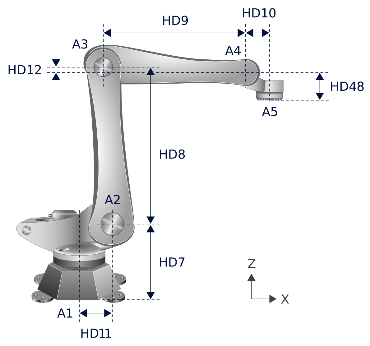
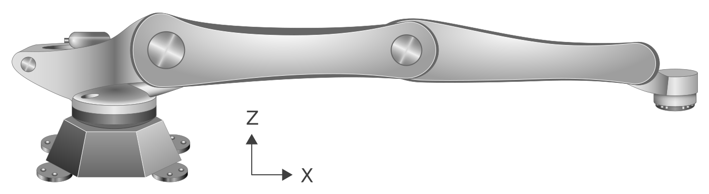
The articulated axes are 1,2,3,4,5. Axis 1 rotates about the z axis of the Cartesian coordinate system. The robot is represented in Figure 2 with all articulated axes in zero position.
 | Functionality available as of CNC Build V3.1.3081 or V3.1.3108. |
Rotation in positive direction corresponds to the mathematically positive direction of rotation in the Cartesian coordinate system. Articulated axes G2, G3, G4 must be configured as linear axes (with a limited range of motion).
Articulated axis G5 must be configured as a modulo axis within the range of -180° to +180°. Optionally, articulated axis G1 can be configured as a linear or a modulo axis, provided no limitations need to be considered, e.g. trailing cables.
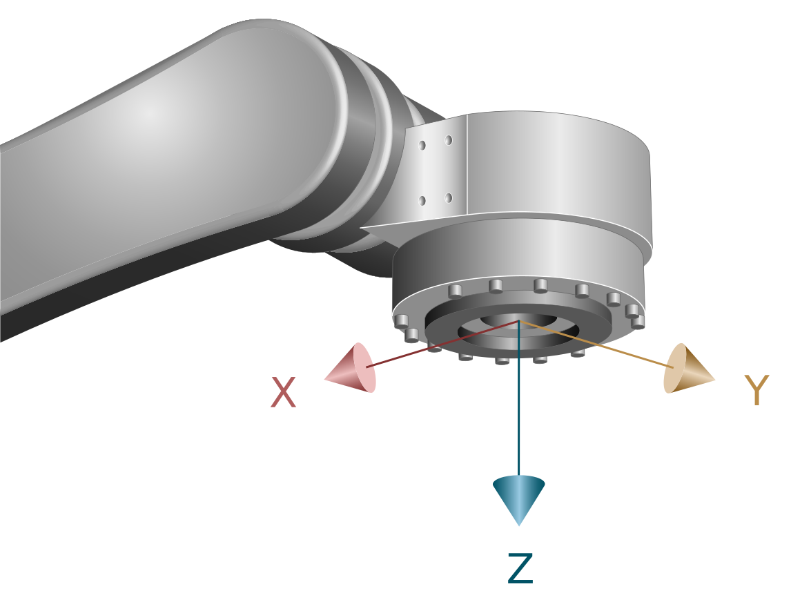
| When programming in Cartesian coordinates, the flange must first be aligned parallel to the X/Y plane of the base coordinate system (B=0). Only then will programming the C angle result in the expected alignment of the flange/tool. However, if the robot is operated with B ≠ 0, the resulting motion may not correspond to the expected orientation. |
| In this kinematic model, the programmed tool orientation normally relates to the Cartesian base coordinate system of the machine. |
Axis configuration in the NC channel | ||
Axis identifier | X, Y, Z, B, C (G1, G2, G3, G4, G5) | |
Axis index | 0, 1, 2, 3, 4 | |
Kinematic structure | ||
| Tool axes | Workpiece axes |
NC axes | X, Y, Z, B, C | - |
Offset data of kinematics
HD offset | param[i] | Description | Unit |
HD1 | 0 | Tool Z offset in flange coordinate system | 1.0 E-4 mm |
HD2 | 1 | Tool X offset in flange coordinate system | 1.0 E-4 mm |
HD3 | 2 | Tool Y offset in flange coordinate system | 1.0 E-4 mm |
HD6 | 5 | Angle of tool rotation about the Z axis | 1.0 E-4° |
HD7 | 6 | Z offset base to G2 | 1.0 E-4 mm |
HD8 | 7 | Offset G2 to G3 | 1.0 E-4 mm |
HD9 | 8 | X offset G3 to G4 | 1.0 E-4 mm |
HD10 | 9 | X offset G4 to G5 | 1.0 E-4 mm |
HD11 | 10 | X offset base to G2 | 1.0 E-4 mm |
HD12 | 11 | Z offset G4 to G3 Note: Positive sign; the rotary axis of joint 3 is located in the positive Z direction above the rotary axis of joint 4. | 1.0 E-4 mm |
HD14 | 13 | Rotary offset for zero position of robot joint axis 2 | 1.0 E-4° |
HD15 | 14 | Rotary offset for zero position of robot joint axis 3 | 1.0 E-4° |
HD21 | 20 | Rotation direction of joint axis 1: 0 (positive), 1 (negative) | [ - ] |
HD22 | 21 | Rotation direction of joint axis 2: 0 (positive), 1 (negative) | [ - ] |
HD23 | 22 | Rotation direction of joint axis 3: 0 (positive), 1 (negative) | [ - ] |
HD24 | 23 | Rotation direction of joint axis 4: 0 (positive), 1 (negative) | [ - ] |
HD25 | 24 | Rotation direction of joint axis 5: 0 (positive), 1 (negative) | [ - ] |
HD36 | 35 | Rotary offset for zero position of robot joint axis 1 | 1.0 E-4° |
HD37 | 36 | Rotary offset for zero position of robot joint axis 4 | 1.0 E-4° |
HD38 | 37 | Rotary offset for zero position of robot joint axis 5 | 1.0 E-4° |
HD48 | 47 | Z offset G4 to G5. Note: Positive sign: Flange is in positive Z direction below G4 | 1.0 E-4 mm |
Programming Example
Five-axis palletising robot