Programming and configuration of 6-axis kinematics (robot) (#ORI MODE)
The evaluation of point-vector programming after selecting the transformation is activated by the NC command #ORI MODE[..]. In conventional point-vector representation, the VECTOR_ABC or VECTOR_IJK mode is used. It remains valid until program end (M30) or until another programmed change occurs. The behaviour of the fixed rotary axis is defined by 2 additional keywords.
Syntax of Point-vector representation |
#ORI MODE [ VECTOR_ABC | VECTOR_IJK FIXED_AX_IDX=.. ] or #ORI MODE [ VECTOR_ABC | VECTOR_IJK TOOL_AX_IN_PLANE=.. ] |
VECTOR_ABC | A, B and C are components of the direction vector. The address letters A, B, C must always be used; they have no reference to configured axis names in the channel list. Vector components need not be specified in standardised form. |
VECTOR_IJK | I, J, K are components of the direction vector. The address letters I, J, K must always be used. Vector components need not be specified in standardised form. It is not permitted to use circular programming by I, J, K at the same time according to DIN 66025.. |
The 2 axes for the rotation angle to the tool orientation are obtained from the 3 vector components.. The angle setting of the third rotary angle is obtained from the joint angle settings at the time when the kinematic transformation is selected and remains unchanged during vector programming.
The axis index of the rotary axis not participating in orientation according to the Euler convention is obtained from considering the order of the axes that define the robot’s position and hand orientation (see also description of P-CHAN-00178).
FIXED_AX_IDX=.. | Axis index of fixed rotary axis. |
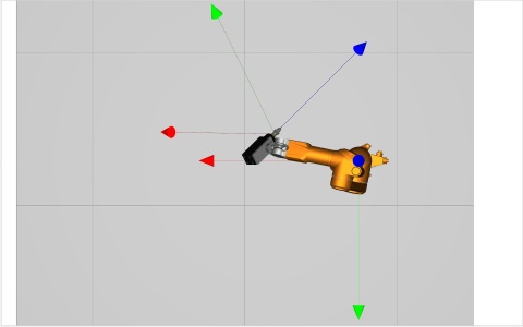
Example: Rotary axis C angle setting 45° on selection, FIXED_AX_IDX = 5
|
|
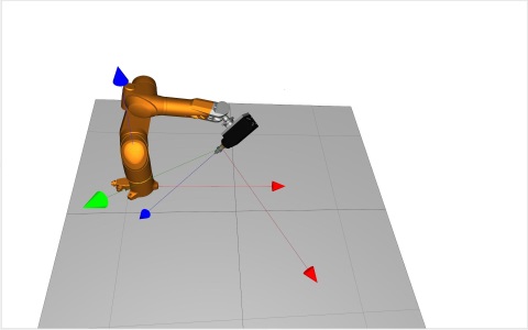

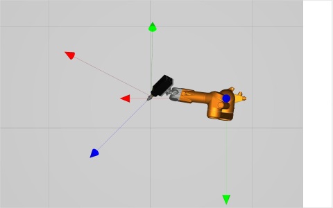
Initial robot orientation Orientation at target point
As an alternative to the fixed rotary axis, it is also possible to define the plane (YZ, ZX) containing either the Z or the Y tool axis. The third angle can then be determined so that the selected tool axis lies parallel to the defined plane at the target point (see also description of P-CHAN-00436).
TOOL_AX_IN_PLANE=.. | Plane parallel to a tool axis. |
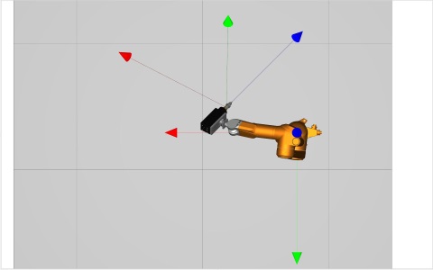
Example 1: Tool axis Z (red) parallel to the basic plane ZX, TOOL_AX_IN_PLANE = 1
|
|
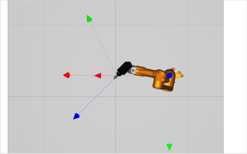
Basic plane ZX: Initial orientation Orientation at target point
Example 2: Tool axis Y (green) parallel to the basic plane YZ, TOOL_AX_IN_PLANE = 2
|
|
Basic plane YZ: Initial orientation Orientation at target point
#ORI MODE [VECTOR_...] causes preselection of orientation programming. Only when the transformation is active (#TRAFO ON) are point-vector representations detected and evaluated
Syntax of Switching over to conventional orientation programming |
#ORI MODE [ ANGLE ] |
ANGLE | Angle values by configured axis names (default). |
Special features relating to active coordinate systems (CS):
- With complete 6-axis transformations and an active CS, orientation is always represented dependent on P-CHAN-00247.
Alternatively, point-vector programming can be preconfigured with P-CHAN-00177. The ori.mode allows the user to define whether values programmed with A, B, C or I, J, K are read in the NC program as normal coordinates or angle values when the kinematic transformation is active or whether the values are interpreted as vector components.
Alternatively, the following identifiers must be configured:
ori.mode | ANGLE | Angle values by configured axis names (default) |
ori.mode | VECTOR_ABC | Vector components by A, B, C |
ori.mode | VECTOR_IJK | Vector components by I, J, K |
If ori.mode is unassigned, the default setting is active for orientation programming (orientation specified by rotation angle).
The axis index of the fixed rotary axis is specified in P-CHAN-00178:
ori.fixed_axis_index <idx> Axis index of fixed rotary axis
The plane parallel to the tool axis is specified in the channel parameter P-CHAN-00436:
ori.tool_ax_in_plane <id> Plane parallel to tool axis plane
Specifications relating to the fixed rotary axis P-CHAN-00178 and the tool axis plane P-CHAN-00436 are mutually exclusive. If the two parameters are assigned, error ID 22027 is output when the controller starts up and the two values are corrected to zero.
Programming Example
Switch over orientation programming to point-vector representation (ABC) and specify fixed rotary axis
Programming Example
Switch over orientation programming to point-vector representation (IJK) and specify the plane parallel to the tool axis