Overview of control loop parameters
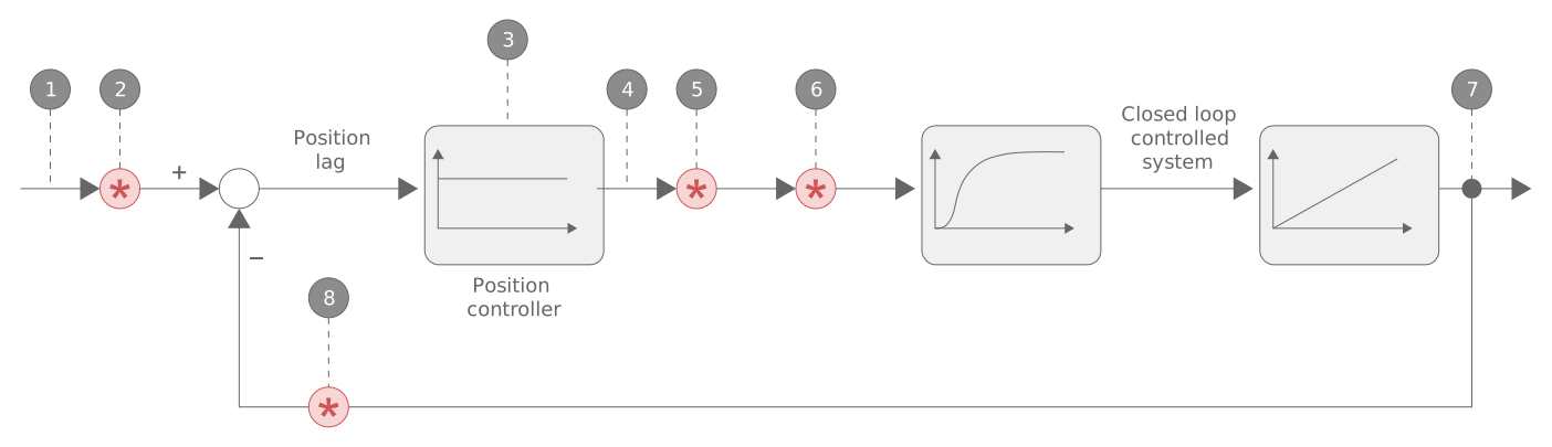
The graphic below shows the position control loop used and the contact points of the drive parameters that are explained in the sections below.
Number | Description |
|---|---|
1 | Command position as input |
2 | Conversion factor for path resolution consisting of P-AXIS-00234/P-AXIS-00233 |
3 | Proportional factor P-AXIS-00099 |
4 | Command velocity as manipulated variable |
5 | Conversion factor for drive format consisting of P-AXIS-00129/P-AXIS-00128 |
6 | Sign reversal of manipulated value P-AXIS-00231 |
7 | Actual position value as output |
8 | Sign reversal of actual value via P-AXIS-00230 |