Description
Task
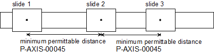
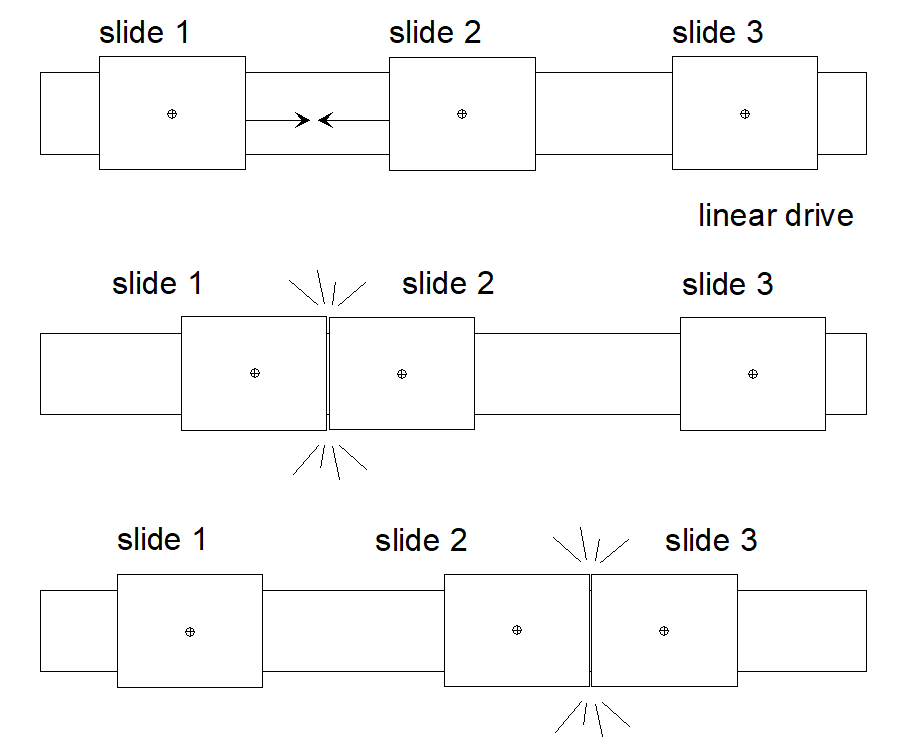
When collision monitoring is used, the position command values of an axis pair generated in the CNC are monitored.
If the distance between two positions undershoots the minimum permitted value with regard to the deceleration distance required for stopping,
- the axes stop immediately depending on the specified dynamic data and
- the CNC outputs the message ID 70092.
After CNC RESET, the two axes must be positioned apart from each other.
Two axes for which the distance is monitored are referred to as a collision pair.
Several collision pairs may be formed.
Notice | |
If the axes are shut down due to detection of a collision, they will generally leave the programmed contour. |
Collision monitoring can be created and activated for each individual axis either
Error response on collision
If the collision axes are in different CNC channels, the parameter P-AXIS-00044 (coll_decelerate_chan) can force a stop in the two channels if a collision axis reports a drive error.
Axis deceleration for collision monitoring
By default the value of P-AXIS-00008 (a_max) is used for collision monitoring to calculate deceleration distances and stop the axes if a collision is detected.
The parameter P-AXIS-00267 (coll_use_a_emergency) can be used to change this deceleration to the value defined in P-AXIS-00003 (a_emergency).
Deceleration distance monitoring
The current velocity of an axis results from:
vt = (setptn - setptn-1) / TA
Where: | vt | current velocity |
The minimum deceleration distance results from the deceleration set for collision monitoring by:
- P-AXIS-00008 (a_max),
- P-AXIS-00267 (coll_use_a_emergency),
- P-AXIS-00003 (a_emergency)
and the current velocity at:
sbrems = ½ (vt2/acoll)
Where: | sbrems | Deceleration distance |