Working Plane and Feed Direction
In order to describe circles (except CIP), and for the compensation of cutter radius and tool length, it is necessary to specify the working plane.
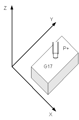
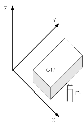
Working Plane XY
Command | G17 (standard setting) |
Cancellation | G18 or G19 |
The function G17 specifies the XY plane as the working plane and the feed direction as the Z direction.
The function acts as:
- Plane for tool radius compensation
- Feed direction for tool length compensation (offset)
- Plane for circle interpolation
 | Changing the working plane The working plane cannot be changed while tool compensation is active. |
Working Plane ZX
|
Command |
G18 |
|
Cancellation |
G17 or G19 |
The function G18 specifies the ZX plane as the working plane and the feed direction as the Y direction.
Working Plane YZ
|
Command |
G19 |
|
Cancellation |
G17 or G18 |
The function G19 specifies the YZ plane as the working plane and the feed direction as the X direction.
Specification of the feed direction
Command | P |
Parameter | + feed direction positive (standard setting) |
Parameterization of the feed direction is required for tool length compensation. It is used to specify whether the tool operates above or below the workpiece.
Sample:
N10 G0 X0 Y0 Z0 F6000
N20 D2 P- Z
N30 G01 X100
N40 D0 Z
N50 M30
In this sample the length compensation operates below the workpiece.