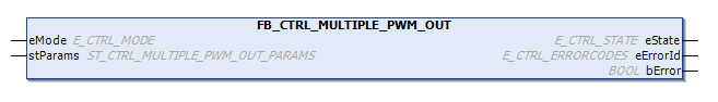
FB_CTRL_MULTIPLE_PWM_OUT
This function block creates PWM modulated output signals from a number of input signals in such a way that the temporal relationships between the output signals are arranged so that as few outputs as possible are switched on at any one time. This temporal arrangement reduces the maximum power necessary required for the actuators.
Both the minimum switch-on time and the minimum switch-off time can be parameterized, in addition to the mark-to-space ratio, in this extended function block.
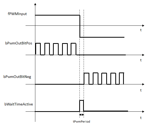
Description of the output behavior 1
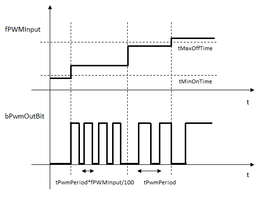
Description of the output behavior 2
The programmer must create the following arrays in the PLC if this function block is to be used:
aPwmInput           : ARRAY[1..nNumPwmOut] OF FLOAT;
aStWaitTimesConfig  : ARRAY[1..nNumPwmOut] OF ST_CTRL_MULTIPLE_PWM_OUT_TIMES;
aStPwmOutputs       : ARRAY[1.. nNumPwmOut] OF ST_CTRL_MULTIPLE_PWM_OUT_OUTPUTS;
aStPwmDataVars      : ARRAY[1.. nNumPwmOut] OF ST_CTRL_MULTIPLE_PWM_OUT_DATA;
The input values for the individual channels of the PWM function block are written into the ar_fPwmInput array. The programmer can specify the parameterizable times for the individual channels in the ar_stWaitTimesConfig array. The function block writes the output bits into the ar_stPwmOutputs array. The internal data required by the function block is stored in the ar_stPwmDataVars array. Under no circumstances should the structures contained in the array ar_stPwmDataVars be changed within the PLC program. This procedure is also illustrated in the sample program listed below.
 Inputs
VAR_INPUT
    eMode    : E_CTRL_MODE;
END_VAR
Name | Type | Description |
|---|---|---|
eMode | E_CTRL_MODE | Input that specifies the operation mode of the function block. |
 Outputs
VAR_OUTPUT
    eState    : E_CTRL_STATE;
    bError    : BOOL;
    eErrorId  : E_CTRL_ERRORCODES;
END_VAR
Name | Type | Description |
|---|---|---|
eState | E_CTRL_STATE | State of the function block |
bError | BOOL | Supplies the error number when the output |
eErrorId | E_CTRL_ERRORCODES | Becomes TRUE, as soon as an error occurs. |
 Inputs/ outputs
VAR_IN_OUT
    stParams    : ST_CTRL_PWM_OUT_EXT_PARAMS;
END_VAR
Name | Type | Description |
|---|---|---|
stParams | ST_CTRL_PWM_OUT_EXT_ | Parameter structure of the PWM element |
stParams consists of the following elements:
TYPE ST_CTRL_MULTIPLE_PWM_OUT_PARAMS :
STRUCT
    tTaskCycleTime            : TIME;
    tPWMPeriod                : TIME;
    nNumberOfPwmOutputs       : USINT;
    pPwmInputArray_ADR        : POINTER TO FLOAT := 0;
    nPwmInputArray_SIZEOF     : UINT;
    pPwmTimesConfig_ADR       : POINTER TO ST_CTRL_MULTIPLE_PWM_OUT_TIMES;
    nPwmTimesConfig_SIZEOF    : UINT;
    pPwmOutputArray_ADR       : POINTER TO ST_CTRL_MULTIPLE_PWM_OUT_OUTPUTS;
    nPwmOutputArray_SIZEOF    : UINT;
    pPwmData_ADR              : POINTER TO ST_CTRL_MULTIPLE_PWM_OUT_DATA;
    nPwmData_SIZEOF           : UINT;
END_STRUCT
END_TYPE
Name | Type | Description |
|---|---|---|
tTaskCycleTime | TIME | Cycle time with which the function block is called. If the function block is called in every cycle this corresponds to the task cycle time of the calling task. |
tPWMPeriod | TIME | Period of the PWM signal |
nNumberOfPwmOutputs | USINT | Number of PWM outputs. [1...n] |
pPwmInputArray_ADR | POINTER TO FLOAT | Address of the PWM input array |
nPwmInputArray_SIZEOF | UINT | Size of the PWM input array in bytes |
pPwmTimesConfig_ADR | POINTER TO ST_CTRL_ | Address of the PWM times array |
nPwmTimesConfig_SIZEOF | UINT | Size of the PWM times array in bytes |
pPwmOutputArray_ADR | POINTER TO ST_CTRL_ | Address of the PWM output array |
nPwmOutputArray_SIZEOF | UINT | Size of the PWM output array in bytes |
pPwmData_ADR | POINTER TO ST_CTRL_ | Address of the internal PWM data array |
nPwmData_SIZEOF | UINT | Size of the internal PWM data array in bytes |
TYPE ST_CTRL_MULTIPLE_PWM_OUT_TIMES :
STRUCT
    tMinOnTime    : TIME;
    tMinOffTime   : TIME;
    tMinWaitTime  : TIME;
END_STRUCT
END_TYPE
Name | Type | Description |
|---|---|---|
tMinOnTime | TIME | Minimum switch-on time of the PWM output |
tMinOffTime | TIME | Minimum switch-off time of the PWM output |
tMinWaitTime | TIME | Waiting time between the switching actions between a positive and negative output signal |
TYPE ST_CTRL_MULTIPLE_PWM_OUT_OUTPUTS :
STRUCT
    bPwmOutBitPos    : BOOL;
    bPwmOutBitNeg    : BOOL;
    bWaitTimeActive  : BOOL;
END_STRUCT
END_TYPE
Name | Type | Description |
|---|---|---|
bPwmOutBit | BOOL | PWM signal, when fPwmInput > 0.0 |
bPwmOutBit | BOOL | PWM signal, when fPwmInput < 0.0 |
bWaitTime | BOOL | A TRUE at this output indicates that the waiting time between the switching actions of the output signals is active. This output can be used to hold an I component that may be present in the prior controller constant during this time. |
TYPE ST_CTRL_MULTIPLE_PWM_OUT_DATA :
STRUCT
Internal structure. This must not be written to.
END_STRUCT
END_TYPE