FB_CTRL_PID_SPLITRANGE
The function block provides an extended PID transfer element in the functional diagram. This controller enables switching between two parameter sets when control is active.
Description
This function block is an extension of FB_CTRL_PID, which means that the controller can be used to control systems with two controlled devices for which the transfer behavior are different. A system with one actuator for heating and another actuator for cooling would be a typical application. To optimize the regulation of such an arrangement, it is possible to switch between two PID parameter sets. Parameter set switchover is implemented in such a way that the control value remains continuous even as the parameter sets are changed.
The switching algorithm calculates a linear, time-dependent transition between the two parameter sets. The nParameterChangeCycleTicks parameter can be used to specify the number of task cycles over which the continuous change between the two parameter sets takes place.
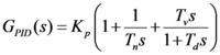
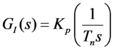
Transfer function
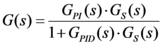
The following transfer function can be specified if the boolean Inputs bPInTheFeedbackPath and bDInTheFeedbackPath are FALSE. Otherwise the transfer function only describes part of the transfer behavior of the function block.
Functional diagram
The standard functional diagram of a PID controller in additive form has been expanded by the two active boolean Inputs bPInTheFeedbackPath and bDInTheFeedbackPath (which act as "switches"), so that a modified functional diagram can be activated.
Control background: due to the differential component of the control algorithm, large control values are generated at setpoint step-changes, which cause a strain on the control elements and may cause the control system to oscillate. A control algorithm with a differential component that is only applied to the controlled variable (bDInTheFeedbackPath := TRUE) can avoid this problem.
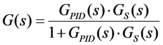
The bPInTheFeedbackPath and bDInTheFeedbackPath Inputs permit the closed control loop to implement the following transfer functions:
bPInTheFeedbackPath | bDInTheFeedbackPath | G(s) |
|---|---|---|
false | false |
|
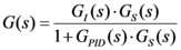
true | false |
|
false | true |
|
true | true |
|

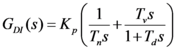
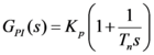
with:
The standard setting for the two bPInTheFeedbackPath and bDInTheFeedbackPath Inputs is FALSE. The PID controller then corresponds to a standard PID controller in additive form.
Step response
ARW

 Inputs
VAR_INPUT
    fSetpointValue      : FLOAT;
    fActualValue        : FLOAT;
    eParameterRecord    : E_CTRL_PARAMETER_RECORD;
    fManSyncValue       : FLOAT;
    bSync               : BOOL;
    eMode               : E_CTRL_MODE;
    bHold               : BOOL;
END_VAR
Name | Type | Description |
|---|---|---|
fSetpointValue | FLOAT | Setpoint of the controlled variable |
fActualValue | FLOAT | Actual value of the controlled variable |
eParameter | E_CTRL_ | Index of the active parameter set |
fManSyncValue | FLOAT | Input with which the PI element can be set. |
bSync | BOOL | A rising edge at this input sets the PI-element to the value "fManSyncValue". |
eMode | E_CTRL_MODE | Input that specifies the operation mode of the function block. |
bHold | BOOL | A TRUE at this input will hold the internal state (and therefore also the output) constant at its current value, independently of the control deviation. |
 Outputs
VAR_OUTPUT
    fOutPos                   : FLOAT;
    fOutNeg                   : FLOAT;
    fOut                      : FLOAT;
    bARWActive                : BOOL := FALSE;
    bParameterChangeActive    : BOOL;
    eState                    : E_CTRL_STATE;
    bError                    : BOOL;
    eErrorId                  : E_CTRL_ERRORCODES;
END_VAR
Name | Type | Description |
|---|---|---|
fOutPos | FLOAT | Output of the PID-element when the control value is positive. A zero is output otherwise. |
fOutNeg | FLOAT | Output of the PID-element when the control value is negative. A zero is output otherwise. |
fOut | FLOAT | Output of the PID element |
bARWActive | BOOL | A TRUE at this output indicates that the PID-element is being restricted. |
bParameter | BOOL | A TRUE at this output indicates that the change from one parameter set to the other is in progress. |
eState | E_CTRL_STATE | State of the function block |
bError | BOOL | Becomes TRUE, as soon as an error occurs. |
eErrorId | E_CTRL_ERRORCODES | Supplies the error number when the output |
 Inputs/ outputs
VAR_IN_OUT
    stParams        : ST_CTRL_PID_SPLITRANGE_PARAMS;
END_VAR
Name | Type | Description |
|---|---|---|
stParams | ST_CTRL_PID_ | Parameter structure of the PID element |
stParams consists of the following elements:
TYPE
ST_CTRL_PID_SPLITRANGE_PARAMS :
STRUCT
    tCtrlCycleTime                : TIME := T#0ms;
    tTaskCycleTime                : TIME := T#0ms;
    fKp_heating                   : FLOAT := 0;
    tTn_heating                   : TIME := T#0ms;
    tTv_heating                   : TIME := T#0ms;
    tTd_heating                   : TIME := T#0ms;
    fKp_cooling                   : FLOAT := 0;
    tTn_cooling                   : TIME := T#0ms;
    tTv_cooling                   : TIME := T#0ms;
    tTd_cooling                   : TIME := T#0ms;
    nParameterChangeCycleTicks    : INT;
    fOutMaxLimit                  : FLOAT := 1E38;
    fOutMinLimit                  : FLOAT := -1E38;
    bPInTheFeedbackPath           : BOOL;
    bDInTheFeedbackPath           : BOOL;
    bARWOnIPartOnly               : BOOL;
END_STRUCT
END_TYPE
Name | Type | Description |
|---|---|---|
tCtrlCycleTime | TIME | Cycle time with which the control loop is processed. This must be greater than or equal to the TaskCycleTime. The function block uses this input value to calculate internally whether the state and the output values have to be updated in the current cycle. |
tTaskCycleTime | TIME | Cycle time with which the function block is called. If the function block is called in every cycle this corresponds to the task cycle time of the calling task. |
Range eCTRL_PARAMETER_RECORD_HEATING: | ||
fKp_heating | FLOAT | Controller amplification / controller coefficient |
tTn_heating | TIME | Integral action time: The I-component is deactivated if this is parameterized as T#0s. |
tTv_heating | TIME | Derivative action time: The D-component is deactivated if this is parameterized as T#0s. |
tTd_heating | TIME | Damping time |
Range eCTRL_PARAMETER_RECORD_COOLING: | ||
fKp_cooling | FLOAT | Controller amplification / controller coefficient |
tTn_cooling | TIME | Integral action time: The I-component is deactivated if this is parameterized as T#0s. |
tTv_cooling | TIME | Derivative action time: The D-component is deactivated if this is parameterized as T#0s. |
tTd_cooling | TIME | Damping time |
nParameter | INT | The number of task cycles over which the change from one parameter set to the other takes place. |
fOutMaxLimit | FLOAT | Upper limit at which integration is halted and to which the output is limited (ARW measure). Reaching this limit is indicated by a TRUE at the |
fOutMinLimit | FLOAT | Lower limit at which integration is halted and to which the output is limited (ARW measure). Reaching this limit is indicated by a TRUE at the |
bPInTheFeed | BOOL | Input value of the P-element can be selected with this input (see functional diagram). |
bDInTheFeed | BOOL | Input value of the D-element can be selected with this input (see functional diagram). |
bARWOnIPartOnly | BOOL | If this parameter is FALSE (the standard setting), the integration of the I-component is halted if the complete controller output reaches the upper or lower limit. If it is TRUE, the integration is halted if the I-component (the output of the integrator) reaches some limit. (Cf. functional diagram.) |