FB_CTRL_PID_EXT
Transfer function
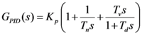
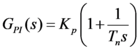
The following transfer function can be specified if the boolean Inputs bPInTheFeedbackPath and bDInTheFeedbackPath are FALSE. Otherwise the transfer function only describes part of the transfer behavior of the function block.
Functional diagram
The standard functional diagram of a PID controller in additive form has been expanded by the two active boolean Inputs bPInTheFeedbackPath and bDInTheFeedbackPath (which act as "switches"), so that a modified functional diagram can be activated.
Control background: due to the differential component of the control algorithm, large control values are generated at setpoint step-changes, which cause a strain on the control elements and may cause the control system to oscillate. A control algorithm with a differential component that is only applied to the controlled variable (bDInTheFeedbackPath := TRUE) can avoid this problem.
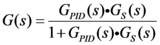
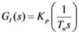
The bPInTheFeedbackPath and bDInTheFeedbackPath Inputs permit the closed control loop to implement the following transfer functions:
bPInTheFeedbackPath | bDInTheFeedbackPath | G(s) |
|---|---|---|
false | false |
|
true | false |
|
false | true |
|
true | true |
|
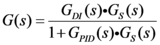
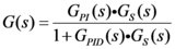
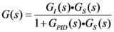
with:
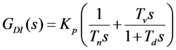
The standard setting for the two bPInTheFeedbackPath and bDInTheFeedbackPath Inputs is FALSE. The PID controller then acts as a standard PID controller in additive form.
Switching off the I-component in the Outer Window
Integration of the control deviation is halted if the control deviation is greater than the fOuterWindow parameter. In this way it is possible to prevent an extremely large I-component from developing if the control deviation is large, since this could lead to a marked overshoot. If it is not wanted, the function can be disabled by setting fOuterWindow := 0.
Linear reduction of the I-component in the Inner Window
With this function it is possible to drive the I-component linearly down to zero in the range specified by the fInnerWindow parameter. If it is not wanted, the function can be disabled by setting fInnerWindow := 0.
Output dead band
If the parameter fDeadBandOutput > 0 is set, the output is set to zero when it is within the range of [ -fDeadBandOutput ... fDeadBandOutput ].
Input dead band
If the parameter fDeadBandInput > 0 is set then the output is held constant for as long as the control deviation remains within the range of [ -fDeadBandInput ... fDeadBandInput ].
Step response
ARW

 Inputs
VAR_INPUT
    fSetpointValue    : FLOAT;
    fActualValue      : FLOAT;
    fManSyncValue     : FLOAT;
    bSync             : BOOL;
    eMode             : E_CTRL_MODE;
    bHold             : BOOL;
END_VAR
Name | Type | Description |
|---|---|---|
fSetpointValue | FLOAT | Setpoint of the controlled variable |
fActualValue | FLOAT | Actual value of the controlled variable |
fManSyncValue | FLOAT | Input with which the PID-element can be set. |
bSync | BOOL | A rising edge at this input sets the PID-element to the value "fManSyncValue". |
eMode | E_CTRL_MODE | Input that specifies the operation mode of the function block. |
bHold | BOOL | A TRUE at this input will hold the internal state (and therefore also the output) constant at its current value, independently of the control deviation. |
 Outputs
VAR_OUTPUT
    fOut                : FLOAT;
    bMaxLimitReached    : BOOL := FALSE;
    bMinLimitReached    : BOOL := FALSE;
    bARWActive          : BOOL := FALSE;
    fCtrlDerivation     : FLOAT;
    eState              : E_CTRL_STATE;
    bError              : BOOL;
    eErrorId            : E_CTRL_ERRORCODES;
END_VAR
Name | Type | Description |
|---|---|---|
fOut | FLOAT | Output of the PID element |
bMaxLimit | BOOL | The output is TRUE when the function block is at its upper limit. |
bMinLimit | BOOL | The output is TRUE when the function block is at its lower limit. |
bARWActive | BOOL | A TRUE at this output indicates that the PID-element is being restricted. |
fCtrlDerivation | FLOAT | The current value of the control deviation |
eState | E_CTRL_STATE | State of the function block |
bError | BOOL | Supplies the error number when the output |
eErrorId | E_CTRL_ | Becomes TRUE, as soon as an error occurs. |
 Inputs/ outputs
VAR_IN_OUT
    stParams    : ST_CTRL_PID_EXT_PARAMS;
END_VAR
Name | Type | Description |
|---|---|---|
stParams | ST_CTRL_PID_ | Parameter structure of the PID element |
stParams consists of the following elements:
TYPE
ST_CTRL_PID_EXT_PARAMS :
STRUCT
    tCtrlCycleTime         : TIME := T#0ms;
    tTaskCycleTime         : TIME := T#0ms;
    fKp                    : FLOAT := 0;
    tTn                    : TIME := T#0ms;
    tTv                    : TIME := T#0ms;
    tTd                    : TIME := T#0ms;
    fDeadBandInput         : REAL := 0.0;
    fDeadBandOutput        : REAL := 0.0;
    fInnerWindow           : REAL := 0.0;
    fOuterWindow           : REAL := 0.0;
    fOutMaxLimit           : FLOAT := 1E38;
    fOutMinLimit           : FLOAT := -1E38;
    bPInTheFeedbackPath    : BOOL;
    bDInTheFeedbackPath    : BOOL;
    bARWOnIPartOnly        : BOOL;
END_STRUCT
END_TYPE
Name | Type | Description |
|---|---|---|
tCtrlCycleTime | TIME | Cycle time with which the control loop is processed. This must be greater than or equal to the TaskCycleTime. The function block uses this input value to calculate internally whether the state and the output values have to be updated in the current cycle. |
tTaskCycleTime | TIME | Cycle time with which the function block is called. If the function block is called in every cycle this corresponds to the task cycle time of the calling task. |
fKp | FLOAT | Controller amplification / controller coefficient |
tTn | TIME | Integral action time; if this is parameterized to T#0s, the I component is deactivated. |
tTv | TIME | Derivative action time; if this is parameterized to T#0s, the D component is deactivated. |
tTd | TIME | Damping time |
fDeadBandInput | REAL | See description above. |
fDeadBand | REAL | See description above. |
fInnerWindow | REAL | See description above. |
fOuterWindow | REAL | See description above. |
fOutMaxLimit | FLOAT | Upper limit at which integration is halted and to which the output is limited (ARW measure). Reaching this limit is indicated by a TRUE at the |
fOutMinLimit | FLOAT | Lower limit at which integration is halted and to which the output is limited (ARW measure). Reaching this limit is indicated by a TRUE at the |
bPInTheFeed | BOOL | Input value of the P-element can be selected with this input (see functional diagram). |
bDInTheFeed | BOOL | Input value of the D-element can be selected with this input (see functional diagram). |
bARWOnIPart | BOOL | If this parameter is FALSE (the standard setting), the integration of the I-component is halted if the complete controller output reaches the upper or lower limit. |