Heartbeat Connection Monitoring
To monitor the connection between LabVIEWTM and TwinCAT, Heartbeat signals can be exchanged periodically between the two systems. This requires corresponding functions on both sides.
 | PLC project required A PLC and a PLC license are required in the TwinCAT project to use Heartbeat Connection Monitoring. |
The following shows how the Heartbeat signals are used to detect an interruption in the connection.
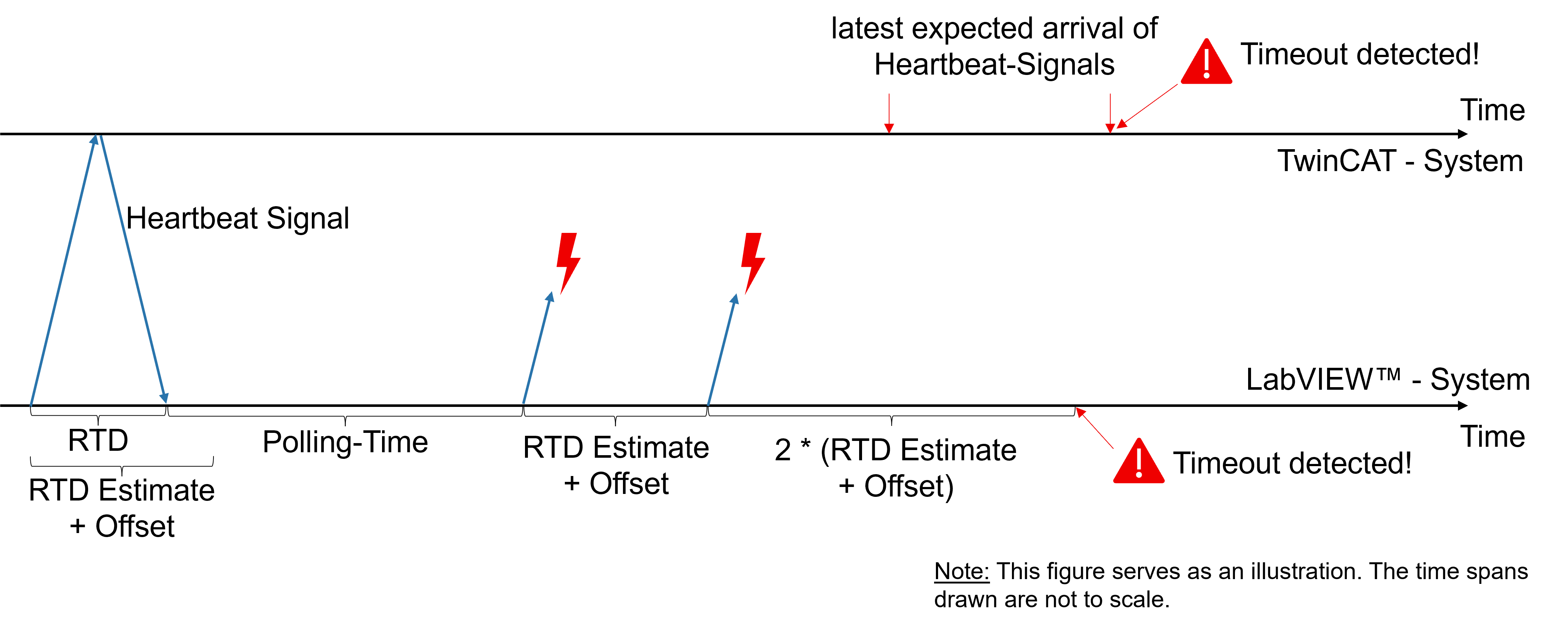
The maximum expected Roundtrip Delay (RTD) is estimated in LabVIEW™ for each Heartbeat signal. This is the time required for the transmitted signal to be received by TwinCAT and sent back again. The estimate is referred to as RTD Estimate. If the Heartbeat signal arrives back in LabVIEW™ within the RTD Estimate (as shown in the figure on the left), the connection is OK. If this is not the case, the connection may be interrupted (as shown in the illustration on the right). To check this, another Heartbeat signal is sent out for validation. This increases the RTD estimate. If this Heartbeat signal also fails, an interruption is detected (timeout detected).
The Heartbeat signals are sent periodically with the polling time T. This is used by TwinCAT 3 to determine the time until which the next Heartbeat signal is expected. If the Heartbeat signal arrives in TwinCAT before this time, the connection is OK. If the Heartbeat signal fails twice in succession, an interruption is also detected on the TwinCAT side (timeout detected).
Roundtrip Delay (RTD) Estimation
Estimating the next maximum expected RTD is central to connection monitoring. The estimation is used both in LabVIEW™ and in TwinCAT. The underlying algorithm is identical in both systems. There are two ways of estimation: dynamic or static.
Dynamic RTD Estimation: In dynamic estimation, the next expected RTD (RTD Estimate) is calculated on the basis of recorded RTDs. A combination of different algorithms is used here. An offset parameter (see below) can be used to influence the estimate. The configured offset is added to the result of the dynamic RTD estimation. This allows the risk of a falsely detected interruption and the response time to be individually adapted to the use case. A larger offset leads to a lower probability of an interruption being falsely detected and at the same time increases the response time of the monitoring.
Static RTD estimation: With static estimation, a constant value is set as the maximum RTD. This value is set by the user via the offset parameter.
Maximum delay until an interruption is detected
The maximum delay until an interruption is detected depends on the estimation method for the RTD.
The following approximation applies to the dynamic estimate:
Response time ≈ Polling time + 3*RTD Estimate + Offset
The following applies approximately to the static estimate:
Response time ≈ polling time + 3* offset
Parameterization
The parameters can be used to influence the behavior of the connection monitoring. The following parameters are available for this purpose:
Name | Name |
|---|---|
Polling time | Timespan in ms that elapses between two Heartbeat signals. |
UseRtdEstimation? | Selection of the method for estimating the RTD |
Offset | Dynamic estimation: Additional waiting time in ms Static estimation: Constant RTD estimate in ms |
| Parameterization only in LabVIEWTM The parameters are configured in LabVIEWTM and automatically adopted by TwinCAT. Parameterization in TwinCAT is not required. |
It makes sense to use the parameters to adjust the behavior of the monitoring to your individual use case. The following considerations should provide support here:
Polling time: The longer the polling time, the longer the response time. At the same time, a shorter polling time leads to more Heartbeat signals being sent, which may increase the network load. The response time of the connection monitoring can be easily set via the polling time (please note that polling time != response time).
| The polling time has no influence on the risk of a falsely detected interruption. |
Offset: The offset can be used to reduce the risk of an incorrectly detected interruption at the expense of the response time.
Creating a function block in TwinCAT
For Heartbeat Connection Monitoring, an instance of the FB_Heartbeat function block must be created for each port in the TwinCAT project for which monitoring is to take place. To do this, the "Tc3_HeartbeatConnectionMonitoring" PLC library must be added in TwinCAT and then an instance of the FB_Heartbeat function block must be created and called.
PROGRAM MAIN
VAR
   fbHeartbeat  :  FB_Heartbeat;
END_VAR
fbHeartbeat();
The function block has outputs that display the state of the connection.
Name | Meaning |
|---|---|
bConnected | Indicates whether there is a connection to the LabVIEWTM system. |
bTimeoutDetected | Indicates whether the connection has been interrupted. |
bStopped | Indicates whether connection monitoring has been stopped from LabVIEWTM. |
AmsAddr | Specifies the target system to which the Heartbeat connection exists. |
Connection monitoring to multiple target systems
A Heartbeat signal from a LabVIEWTM project can be received for each instance of FB_Heartbeat, but a LabVIEWTM project can realize connection monitoring to several TwinCAT systems.