PLC API
The TwinCAT3 Condition Monitoring Library provides analysis options in a TwinCAT PLC application. Please refer to our product description and the technical introductions for an overview and important background information on the product.
The PLC API sets consist of three PLC libraries. These libraries have to be integrated in a Condition Monitoring PLC project:
- Tc3_CM
- Tc3_CM_Base
- Tc3_MultiArray
Condition Monitoring analysis
In addition to programming, which includes logging of the measured data, processing based on different algorithms and evaluation of the results, each signal processing relies on an appropriate analysis chain. For that reason the TwinCAT 3 Condition Monitoring Library supports you with function blocks that turn the implementation of the planned analysis chain into virtually pure parameterization work.
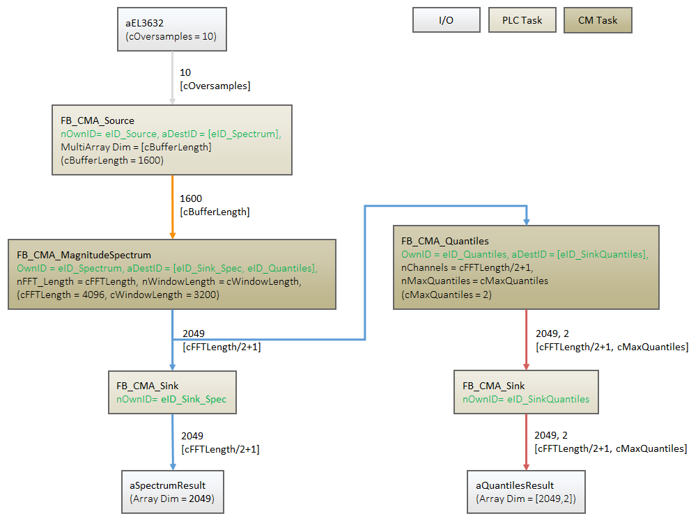
Analysis chain as diagram
It makes sense to create a diagram (example see below) regarding the analysis steps before programming the Condition Monitoring application!
It includes a representation of each PLC function block. Usually at least two tasks are used, one task for the regular control program and another (slower and lower priority) task for the computationally intensive operations of Condition Monitoring.
Each analysis function block uses a special way of communicating with each other. This internal implementation also enables cross-communication across multiple tasks. Internally, one TransferTray object and several MultiArrays are used (see chapter Parallel processing). However, a function block or its methods may only be called from a task context in the application!
The analysis function blocks can be placed in different task contexts. The sequence of the analysis steps is assigned using transfer IDs (green values in the figure below). Each function block receives its own arbitrary ID and the target ID(s) to which the results are to be sent. The transfer IDs are best defined as enumeration.
The diagram below shows four different data buffers: gray, orange, blue and red. The shape of all corresponding buffers (PLC arrays, MultiArrays) and the algorithm parameters must match these buffer sizes.
 | Cyclic call As long as the functionality of FB_CMA_Source is called and signal data is transferred to a target function block, all other modules of the analysis chain must be called cyclically. See description of the internal communication principle in chapter Parallel processing. If not all target blocks are to be processed during a particular phase, their call is still necessary, but the PassInputs() method can be used to pass only the input buffers without producing results. |
| Note consequential errors A cyclically recurring error in an analysis function block can cause consequential errors in the analysis chain. |
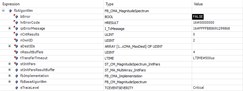
Online View
The function blocks of the Condition Monitoring library hold significant information about the current state of the function block in the Online View. These can be used for the programming of the application (initialization and configuration of the function blocks, adjustment of the buffer sizes in the analysis chain, etc.) as well as the analysis and evaluation (error analysis, graphic display).
The graphic below shows the Online View of the function block FB_CMA_MagnitudeSpectrum. Some nodes and their possible uses are explained in more detail below.
Return values
In case of error, bError := TRUE is set and the return value hrErrorCode contains the error code; see Error Codes Overview.
When processing several channels (nChannels > 1), there is a possibility of each channel having different return values. In this case, return values can be queried separately on the function block. If the results from one or more channels are impermissible, but not all channels, the value on the function block corresponds to eCM_InfRTime_AmbiguousChannelResults. If the results of all channels are impermissible, then the value on the function block corresponds to eCM_ErrRTime_ErrornousChannelResults.
The reading of the error list and an example of the handling can be found in the example Multi-channel magnitude spectrum.
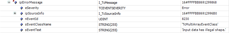
Error description and information
More detailed information about the current return value can be found in ipErrorMessage. sEventText shows the text description of an error that has occurred. Depending on the setting of TcEventSeverity (initial parameter eTraceLevel, see also Param setting), this message is output via the TC3 EventLogger.
Initial parameters
The initial parameters of the function block, which are adopted in the course of the initialization phase of the PLC, are stored under the node stInitPars.
For all function blocks that have an adjustable overlap (nOverlap parameter), the calculated recommended value (in the case of nOverlap := cCM_OverlapRecommended) can be read in the named node after the login of the PLC. This can subsequently be used for the adjustment of the data buffer (Input/Output Shape) in the analysis chain. It is not necessary to start an application for this.
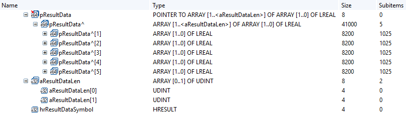
ADS access to result data
Each analysis function block has the sub-node pResultData, which is only visible in the TwinCAT Target Browser. The results (MultiArrays) sent between various function blocks in an analysis chain can thus be read via ADS. This enables the simple graphic display of the results of a function block by means of the Overview without the results first having to be converted from a multi-array into a PLC array via a sink function block.
| The function described requires TC3 Scope View from Version 1.4.3141 (available among other things with TwinCAT from Version 3.1.4024.7). |