Basic principles
The UML state diagram is a graphical formalism to specify and design the sequence of a system with discrete events or to program a time behavior. Integrated in the PLC area of the TwinCAT 3 development environment, a state diagram has an editor with state and transition elements. When the application is compiled, executable code is generated. By default, the switching behavior of a state diagram is clocked depending on the task cycle when it is executed, but depending on how the states are configured, it can also switch independently. In this case, these are cycle-internal states. Powerful functionalities such as syntax monitoring or debugging in online mode support the development process.
Application case
A Statechart is used for programming time-discrete systems. Programs, function blocks, functions, methods or actions can be created as a graph from states and transitions with the Statechart implementation language.
Functions/methods and their data are normally temporary. If you implement a function/method with the UML Statechart implementation language, the chart contains cycle-internal states and re-initializes the data at the start of the task cycle.
With methods, conversely, there is a possibility to declare the method as VAR_INST. The data are then retained as with a function block and are not temporary, therefore the Statechart will be run through in several task cycles as usual. Refer also to Option UseVarInst regarding this. This option is not available with functions.
Syntax
The syntax is under compiler control:
- a transition between states lying in different regions are not allowed
- orthogonal states cannot be nested in other states
- exactly one exception transition or completion transition is allowed to exit a composite state
- a conditional transition going into an orthogonal state is not allowed, then a fork/join is required
Commands
The following commands or action options are available for the Statechart:
Also note the commands, which are available for all UML diagrams: Common commands for all UML diagrams.
Implicit variables of a state diagram
The implicit variables are located in the program unit that maps the state diagram (e.g. in the instance of the function block or in a program). The internal variables are located inside the program unit under the element name "UML_SC_<POU name>" with the data type "UML_SC_<id>".
For the function block "FB_UML", the element name of the implicit variables is "UML_SC_FB_UML", for example. They are located in the function block instance "fbUml".
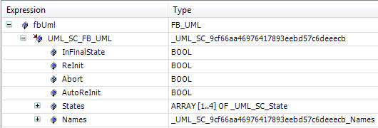
"UML_SC_<POU name>" of the data type _UML_SC_<id>:
Some implicit variables reflect the state of the object during the runtime (InFinalState, States), while others serve to control the behavior at runtime (Reinit, Abort, AutoReInit).
Name | Data type | Meaning |
|---|---|---|
InFinalState | BOOL | This variable has the value TRUE if the state diagram is in the end state. |
ReInit | BOOL | Setting this variable to TRUE will cause the state diagram to be re-initialized, i.e. the start state of the diagram is activated. |
Abort | BOOL | Setting this variable to TRUE will cause the current operation of the diagram to be aborted and the end state of the diagram to be activated. |
AutoReInit | BOOL | If the value of this variable is TRUE, the start state of the diagram is automatically restored as soon as the end state is reached. Default value: TRUE |
States | ARRAY[<number of states>] OF _UML_SC_State | see below |
Names | _UML_SC_<id>_Names | see below |
"UML_SC_<POU name>.States" of the data type ARRAY[<number of states>] OF _UML_SC_State:
The variables of the structure _UML_SC_State serve to describe a state. This data type is the base type of an array with the name "States", which is declared in the implicit variables and describes the individual states of the state diagram.
The individual variables of the structure _UML_SC_State are described in the following table.
Name | Data type | Meaning |
|---|---|---|
Active | BOOL | Flag for determining whether the state is currently active. |
FastExecutionFault | BOOL | Relevant for IntraCycle states: if an IntraCycle state is active for longer than a cycle, this flag is set by the system. The flag is reset on exiting from the IntraCycle state. |
ID | INT | ID of the state The ID of the state corresponds to the index at which the state is described in the "States" array. |
ActivationTime | TIME | Time stamp of the last activation of the state |
Name | STRING | Name of the state |
"UML_SC_<POU name>.Names" of the data type _UML_SC_<id>_Names:
The data type _UML_SC_<id>_Names contains an INT variable for each state of the state diagram. This variable is declared with the name of the state and its value indicates the ID of the state. The ID of the state corresponds to the index at which the state is described in the "States" array.
Name | Data type | Meaning |
|---|---|---|
<Name of the state> Example: StartState1 | INT | ID of the state (= index at which the state is described in the "States" array) Example: ID of the state "StartState1", e.g. 4 |
<Name of the state> Example: State1 | INT | ID of the state (= index at which the state is described in the "States" array) Example: ID of the state "State1", e.g. 5 |
<Name of the state> Example: State2 | INT | ID of the state (= index at which the state is described in the "States" array) Example: ID of the state "State2", e.g. 6 |
… | … | … |
Example:
A function block is created with the implementation language UML SC and the name "FB_UML". The statechart diagram has a state named "MyStateName". The FB also contains the "MyMethod" method in the ST language. In the following sample, it is queried from inside and outside the FB whether the statechart diagram is currently in the "MyStateName" state.
Access from inside the FB / in FB_UML.MyMethod:
FUNCTION_BLOCK FB_UML
VAR
    bInSpecificState : BOOL;
    …
END_VAR
METHOD MyMethod : BOOL
bInSpecificState := UML_SC_FB_UML.States[UML_SC_FB_UML.Names.MyStateName].Active;Access from outside the FB / in MAIN:
PROGRAM MAIN
VAR
    fbInstance       : FB_UML;
    bInSpecificState : BOOL;
END_VAR
fbInstance();
fbInstance.MyMethod();
bInSpecificState := fbInstance.UML_SC_FB_UML.States[fbInstance.UML_SC_FB_UML.Names.MyStateName].Active;