Interface
An interface defines methods and property declarations that describe an externally visible behavior. It contains no variables and no implementation, but only the definition of methods and/or properties. An interface is a variable type that can be instantiated.
An interface can have the following relationship type:
- Generalization: An interface can inherit from another interface.
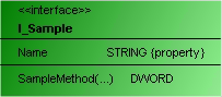
Like classes, interfaces are shown divided into three parts. The rectangle is green and overwritten with <<interface>>. The interface name follows below in bold. The interface properties are displayed after the first dividing line, based on the following syntax:
<property name>: <data type> {property}
All interface methods follow after the second dividing line. After the method name there may be a reference to the variable transfer in parentheses. If a return type is declared for a method, this follows in the right-hand column.
<method name>(…): <return type>
Properties
|
“Property” |
Description |
|---|---|
|
“Identifier” |
Insert here an unique name for the selected element. The name can be modified here, however also within the class diagram by selecting the name and then opening an inline editor by a further mouse click. |
Edit interface
The following user inputs are available if “Selection” is enabled in "Toolbox" (default).
|
User input in the class diagram |
Response in the class diagram |
Description |
|---|---|---|
|
Select the tool "Interface":
Click in an empty area of the diagram. The dialog “Add interface” opens. Enter a name for the new object, adjust the settings and close the dialog with "Add". |
An interface is created. |
The object exists in the diagram and in the project. The view in the project tree is updated automatically. |
|
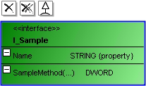
Click on an interface icon. |
|
To the left above the interface, icons are now visible, which make it possible to add relationship elements. The example on the left has expanded property and method lists after |
|
Click on |
The interface is only removed from the diagram. |
Use "flat" removal of an interface to remove it from the class diagram view only. The object still exists and is visible in the project tree. |
|
Click on |
The interface is removed from the diagram and the project. |
The object is removed. It then no longer exists. |
|
Click on |
A generalization points from the existing interface outward to the new interface. The existing interface inherits from the new interface. |
The existing interface contains the declaration. Example: INTERFACE I_Sample EXTENDS I_New Keep in mind that the default settings in the dialog 'Add interface' originate from the last application of this dialog. |
|
Click on |
A generalization points from the second interface to the first interface. |
The first interface contains the declaration. Example: INTERFACE I_Sample EXTENDS I_Existent |
|
Click on |
|
The property or method list is minimized. |
|
Click on |
|
The property or method list is expanded. |
|
Click on the name. Once it is selected, click on it once again. |
After the first click, the name has a blue border. After the second click the line editor opens. |
Change the interface name in the line editor. The change is applied synchronously and automatically to the project. That is, the object name in the project tree and in the declaration section of the POU is adjusted immediately. |
|
Double-click on an interface. |
The corresponding object editor opens with the declaration editor. |
Edit the declaration. After closing of the object you are returned to class diagram. The changes are automatically applied to the class diagram. |

 .
. .
. .
. and then in an empty area of the diagram. The dialog “Add interface” opens. Enter a name and exit the dialog with "Add".
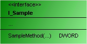
 .
.Example
- Generalization
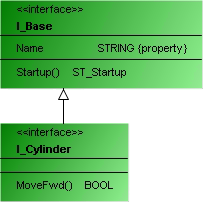
INTERFACE I_Cylinder EXTENDS I_Base