Class
A class is a logical unit in which data and operations are encapsulated. It also represents a variable type that can be instantiated. A class can have an FB_Init method that is called when an instance is initialized.
A class can have the following relationship types:
- Composition: a class can contain other program elements.
- Association: a class can know other program elements.
- Realization: a class can implement an interface.
- Generalization: a class can inherit from another class.
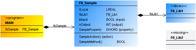
A class is represented by a three-part rectangle.
- Orange with heading <<program>>: POU (PROGRAM)
- Blue without heading: POU (FUNCTION_BLOCK or FUNCTION)
- Blue with heading <<library>>: POU (FUNCTION_BLOCK or FUNCTION) from a library (library function block)
- Greyed with heading <<missing>>: POU (FUNCTION_BLOCK or FUNCTION) from a library, which is currently not integrated in the project
The class name follows in bold.
All attributes are shown after the first dividing line. Each visible attribute has an identifier. If {input} in curly brackets is appended, it is a variable of type VAR_INPUT; {output} indicates a variable of type VAR_OUTPUT. A property has the ID {property}. An internal (non-visible) variable of type VAR has no ID:
<Attribute name> : <Data type> {'{input}' | '{output}' | '{property}'}
The second dividing line is followed by all operations for the class, i.e. its methods or actions. The name of the operation is followed by closing parentheses. This is followed by {action} to identify an action:
<action name>() {action}
If it is a method, the parentheses may indicate a variable transfer. If a return type is declared for a method, this follows in the right-hand column. Unlike actions ({action}), methods have no concluding ID:
<Method name>(…) : <Return type>
Properties
|
“Property” |
Description |
|---|---|
|
“Identifier” |
Class name Sample: FB_EventLogger |
User inputs for a class
The following user inputs are available if “Pointer” is enabled in the toolbox (default).
User input in the class diagram | Response in the class diagram | Description |
|---|---|---|
Select the tool “Class (POU)”:
Click in an empty area of the diagram. The dialog “Add POU” opens. Enter a name for the new object, adjust the settings and close the dialog with "Add". | A class is created. | The object exists in the diagram and in the project. The view in the project tree is updated automatically. |
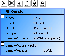
Select a class. |
| The class has expanded attribute and operation lists, which are identified with Command icons for adding relationship elements are now visible to the left above the class. Tip: If the class has relationships that are currently not shown in the class diagram (missing rectangular elements), a list of “Incoming cross-references” and/or “Outgoing cross-references” appears in the "Toolbox" view. Below this the missing rectangular elements are listed, which you can drag & drop into the class diagram for display. |
Click on | The class is removed in the diagram, so that it is no longer displayed. | Use "flat" removal of a class to remove it from the class diagram view only. The object still exists and is visible in the project tree. Tip: The class is shown in “Toolbox” under “Incoming cross-references” and/or “Outgoing cross-references”, if a rectangle element with a relationship to the remote element is selected in the class diagram. |
Click on | The class is removed from the diagram and the project. | The object no longer appears as object in the class diagram or the project tree. It no longer exists. |
Click on | A composition arrow points from the existing class to the new class. | The existing class contains an instance pointing to the new class. Sample: fbNew : FB_New; |
Click on | A composition arrow points from the first class to the second class. | The first class contains an instance pointing to the second class. Sample: fbExistent : FB_Existent; |
Click on | A new class with an association arrow pointing to the existing class is created in the diagram. | A new class FB_New is created. The existing class now knows the new class and contains an association with the new class. Sample: pNew : POINTER TO FB_New . |
Click on | An association arrow points from the second class to the first class. | The first class knows the second class. It now contains a new variable of type. Sample: pExistent : POINTER TO FB_Existent; |
Click on | A generalization points from the existing class to the new class. The existing class inherits from the new class. | The existing class contains the declaration. Sample: FUNCTION_BLOCK FB_Sub EXTENDS FB_New |
Click on | A generalization points from the first class to second class. | The first class contains the declaration. Sample: FUNCTION_BLOCK FB_Sub EXTENDS FB_Existent |
Click on | A realization arrow points from the class to the new interface. | The class implements the new interface. The declaration section of the class contains. Sample: FUNCTION_BLOCK FB_Sample IMPLEMENTS I_SampleNew |
Click on | A realization arrow points from the class to the interface. | The class now implements the interface. The declaration section of the class contains. Sample: FUNCTION_BLOCK FB_Sample IMPLEMENTS I_SampleExistent |
Click on |
| The attribute or operation list is minimized. |
Click on |
| The attribute or operation list expands. |
Click on the class name. Once it is selected, click on it once again. | After the first click, the name has a blue border. After the second click the line editor opens. | The change is applied synchronously and automatically to the project. That is, the object name in the project tree and in the declaration section of the POU is adjusted immediately. |
Click twice on an attribute or operation name. Then change the name in the line editor. | After the first click, the name has a blue border. After the second click the line editor opens. | The change is applied synchronously and automatically to the project. |
Double-click on the class element. | The corresponding object editor opens, and the declaration and implementation are displayed. | You can change the declaration or the implementation. After closing of the object you are returned to class diagram. The changes are automatically applied to the class diagram. |

 .
. .
. .
. and then in an empty area of the diagram. The dialog “Add POU” opens. Enter a name for the new object, adjust the settings and close the dialog with "Add".
 and then in an empty area of the diagram. The dialog “Add POU” opens. Enter a name for the new object, adjust the settings and close the dialog with "Add".
 and then in an empty area of the diagram. The dialog “Add POU” opens. Enter a name, adjust the settings and close the dialog with "Add".
 and then in an empty area of the diagram. The dialog “Add interface” opens. Enter an interface name, adjust the settings and close the dialog with "Add".
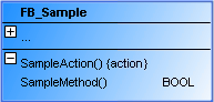
 .
. | Keep in mind that the default settings in the dialog 'Add POU' or 'Add interface' originate from the last application of this dialog. |
Samples
- Composition
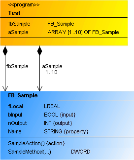
PROGRAM Test
VAR
    fbSample      : FB_Sample;
    aSample       : ARRAY[1..10] OF FB_Sample;
END_VAR- Association
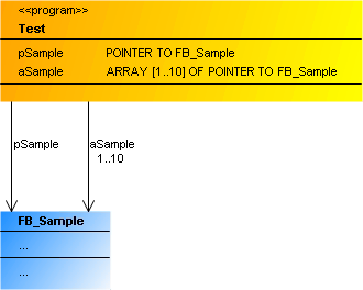
PROGRAM Test
VAR
    pSample     : POINTER TO FB_Sample;
    aSample     : ARRAY[1..10] OF POINTER TO FB_Sample;
END_VAR- Generalization
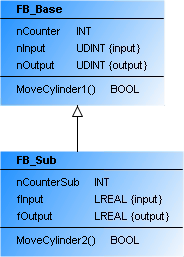
FUNCTION_BLOCK FB_Sub EXTENDS FB_Base- Implementation
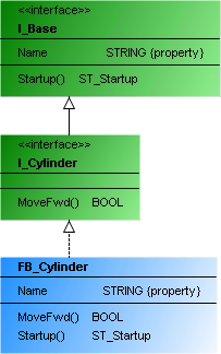
INTERFACE I_Cylinder EXTENDS I_BaseFUNCTION_BLOCK FB_Cylinder IMPLEMENTS I_Cylinder