AM8xxx Smart System Diagnosis
The AM8xxxSSD enables the analysis of a motor equipped with the Smart System Diagnosis functionality. The built-in encoder records measured values from various internally installed sensors. These include the temperature and humidity in the encoder, as well as the acceleration in the X and Y directions. Various statistical parameters are calculated on the basis of these measured values and threshold monitoring is carried out to detect shocks.
Optionally, a Boolean signal can be selected for the Enable Execution input so that the algorithm is only active if the value of the selected signal is TRUE.
Configuration options
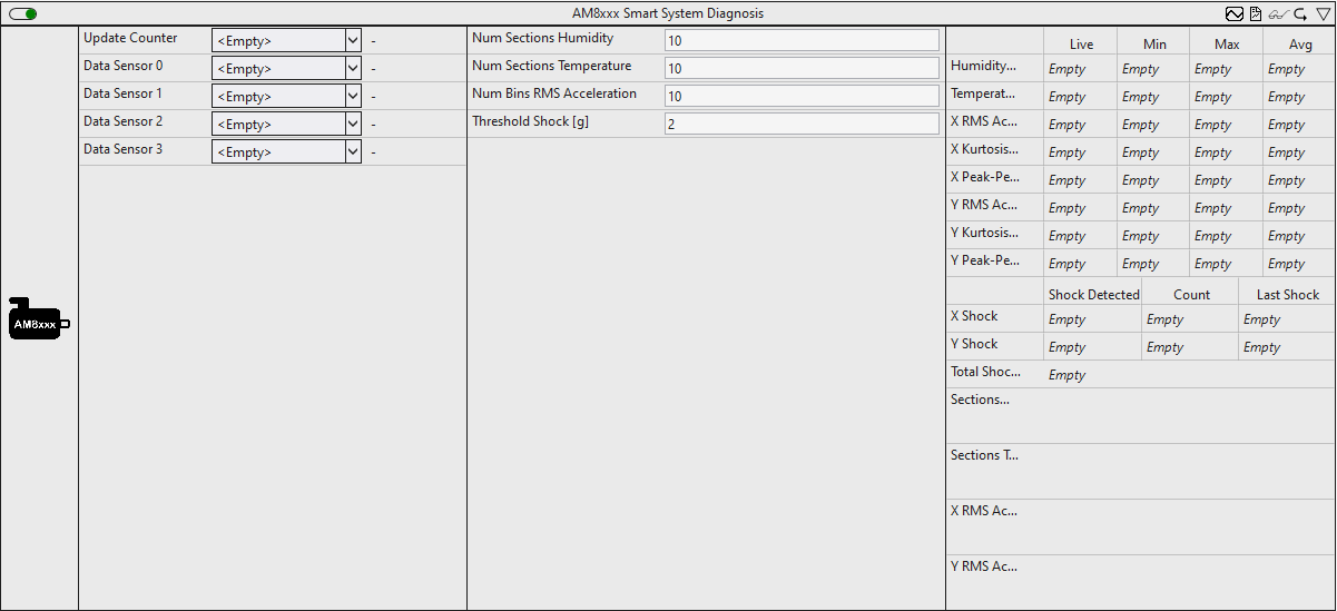
- Num Sections Humidity: Configure the number of sections for analyzing the humidity in the encoder.
- Num Sections Temperature: Configure the number of sections for analyzing the temperature in the encoder.
- Num Bins RMS Acceleration: Configure the number of histogram bins for analyzing the acceleration.
- Threshold Shock: Threshold value for the RMS of the acceleration for detecting shocks.
Output values
- Humidity: Minimum, maximum and average value of the humidity within the encoder in %.
- Temperature: Minimum, maximum and average value of the temperature within the encoder in °C.
- X RMS Acceleration: Minimum, maximum and average value of the RMS acceleration in the X direction in g.
- X Kurtosis Acceleration: Minimum, maximum and average value of the kurtosis of the acceleration in the X direction.
- X Peak-Peak Acceleration: Minimum, maximum and average value of the peak-peak value of the acceleration in the X direction in g.
- YRms Acceleration: Minimum, maximum and average value of the RMS acceleration in the Y direction in g.
- Y Kurtosis Acceleration: Minimum, maximum and average value of the kurtosis of the acceleration in the Y direction.
- Y Peak-Peak Acceleration: Minimum, maximum and average value of the peak-peak value of the acceleration in the Y direction in g.
- X Shock | Shock Detected:
TRUE, if a shock is detected in the X direction. The threshold value of the RMS acceleration is monitored for this purpose. - X Shock | Count: Number of shocks in the X direction.
- X Shock | Last Shock: Timestamp of the last detected shock in the X direction.
- Y Shock | Shock Detected:
TRUE, if a shock is detected in the Y direction. The threshold value of the RMS acceleration is monitored for this purpose. - Y Shock | Count: Number of shocks in the Y direction.
- Y Shock | Last Shock: Timestamp of the last detected shock in the Y direction.
- Total Shocks: Number of shocks in the X and Y direction.
- Sections Humidity: Temporal distribution of humidity within the encoder. (Section Timer)
- Sections Temperature: Temporal distribution of the temperature within the encoder. (Section Timer)
- X Rms Acceleration: Distribution of the acceleration in the X direction. (Histogram)
- Y Rms Acceleration: Distribution of the acceleration in the Y direction. (Histogram)
Standard HMI Controls
For the algorithm, the following HMI controls are available for generating an Analytics Dashboard:
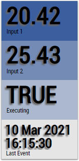
1. The specific AM8xxx Control visualizes the output values and displays them graphically.
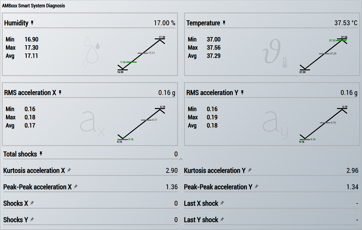 Fig.1:
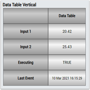
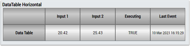
 2. The Table Control or List Control visualizes all output values
Preparation
In order for the sensor values to be available for analysis, they must be added to the process image of the drive. This process is described below.
- 1. Create a TwinCAT project.
- 2. Scan the I/Os of the TwinCAT project.
- 3. Add a Drive Manager project to the solution.
- 4. Select the corresponding channel of the drive to which the motor with the B/SSD-capable encoder is connected.
- 5. Select the Advanced tab.
- 6. Further process data can be added in the Process data subitem.
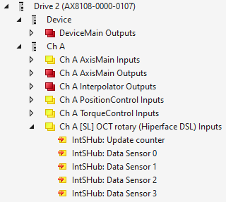
- 7. Add the following process data:
IntSHub: Update counter
IntSHub: Data Sensor 0
IntSHub: Data Sensor 1
IntSHub: Data Sensor 2
IntSHub: Data Sensor 3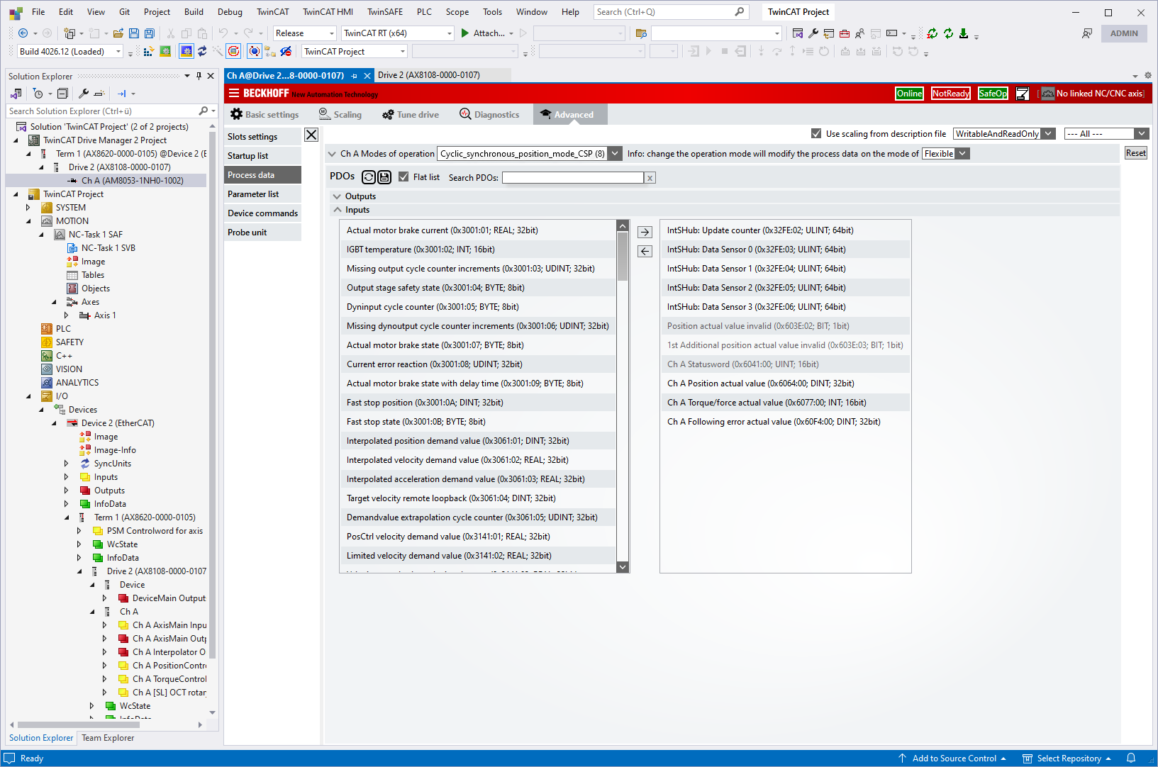
- Once the process data has been added, it is displayed in the I/O node and is available for analysis.