Vision Gallery
The “Vision Gallery” is designed as a toolbox for in-depth analysis and documentation.
- Long-term viewing: Images can be stored over a longer period of time and saved in a targeted manner.
- Comparison function: It is possible to save reference images from previous analysis times in order to compare them directly with current results.
- Interaction: The tool offers the option of making markings in the images to highlight special features or sources of error.
Integration in Visual Studio
The following figure shows the integration within the Visual Studio environment:
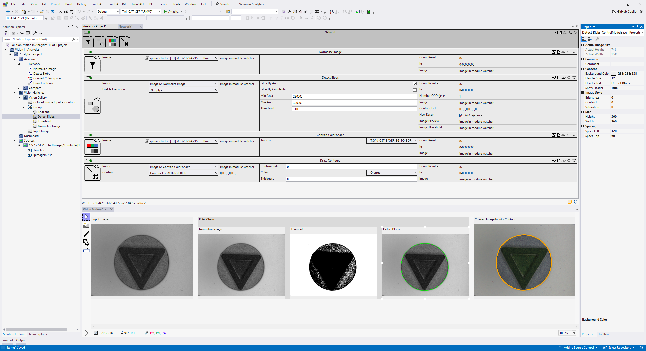
All instances of the Gallery are managed centrally in the Solution Explorer under the dedicated “Vision Galleries” node. This enables quick access to analysis layouts that have already been created within your solution.
There are several ways to add a new Vision Gallery:
- Via the Solution Explorer:
Right-click on the “Vision Galleries” node and select the command to create a new gallery from the context menu. - Directly from the analysis (context menu):
You can also create a new gallery directly from the workflow. To do this, right-click on any Image In or Out variable in the Network Editor or in the Module Watcher and select the corresponding option in the context menu.
The fine-tuning of the Gallery and the objects it contains is done via the standard Visual Studio Properties window. As soon as you select an item within the Gallery, all editable parameters are displayed there.
By linking to the Analytics Timeline, you can also navigate specifically through the analysis period in order to view historical image data in detail.
Adding analysis images
There are two methods available for transferring image data to a Gallery:
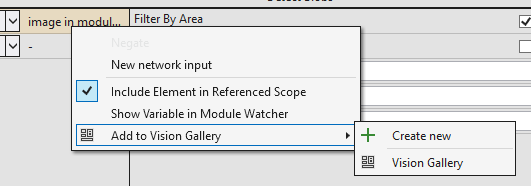
- Via the context menu
Right-click on the desired image variable in the network editor. Using the context menu (see illustration below), you can either assign the image to an already open Gallery or create a new Gallery instance directly. - Drag and drop:
Drag the variable with the mouse directly from the network editor into the Gallery window. The decisive advantage here is that the image is placed exactly at the position at which you release the mouse button. This allows you to design your layout intuitively.
Toolbox
The toolbar is located on the left-hand side of the Gallery. To activate a Toolbox, select the corresponding icon in the list. Two creation methods are available for all Toolboxes that create new objects (e.g. shapes, lines or additional images):
- Double-click to create:
Double-click at the point in the Gallery where the object is to be placed. The item is then automatically created in a predefined standard size (default) at this position. - Creation by dragging:
To define the size of the object directly when creating it, click on the desired start point and drag the item while holding down the mouse button. As soon as the desired dimensions are reached, release the mouse button.
Below you will find an overview of the Toolboxes available for customizing and annotating your Gallery:
| Cursor (selection tool): This is the standard tool of the Gallery. It is automatically active if no other drawing tool has been chosen. When the cursor is active, you can select existing objects in the Gallery by clicking on them. A selected object can then be moved freely on the workspace or its size can be adjusted (scaled) using the handles on the corners and edges. |
| Image tool: Allows you to manually insert additional graphics. The property grid can be used to load images from the hard disk, for example to store static reference images for direct comparison in the Gallery. |
| Line tool: Used to mark and measure image areas. When drawing on an image, the exact length and angle of the line are automatically displayed below the image. Particularly efficient: The determined angle can be transferred directly to parameters in the Workbench (e.g. for the Rotate Image function block). The line thus functions as an interactive configuration aid for image alignment. |
| Shape tool: Enables the insertion of geometric objects, whereby a rectangle is created by default. The property grid can be used to switch the type flexibly between rectangle, circle and arrow. |
| Text tool: Allows you to add individual texts and descriptions within the Gallery. This allows analysis results to be documented directly in the view or prepared for other users in an understandable way. |


Object manipulation
The handling of objects within a gallery follows common standards of advanced graphic tools, which enables intuitive operation.
The following functions are available for all placed items:
- Move: Selected objects can be freely positioned on the workspace using the mouse.
- Scaling: The size of an object can be individually adjusted at any time using the handles on the corners and edges.
- Grouping: Several objects can be grouped together so that they can be moved or aligned together. Management is carried out in the Solution Explorer either via the context menu or intuitively via drag and drop.
Particularly important: Objects that are placed on a picture are automatically grouped with it. In this case, the coordinates of the object (e.g. position of a rectangle) do not refer to the Gallery area, but to the native pixel coordinates of the image. This means that markings remain absolutely true to position even when the image is scaled or moved.
Additional interactions
The information bar is located at the bottom of the Gallery (see illustration below). All values displayed there refer to the original dimensions of the image and are independent of the current scaling or display size within the Gallery.

- Image dimensions (left): Shows the actual resolution of the currently selected source image in pixels.
- Cursor position (center): Specifies the exact pixel coordinates (X/Y) of the current mouse position within the image that is currently under the cursor.
- Color value display (right): Displays the RGB color value of the image pixel located directly under the mouse cursor. This enables a quick check of color and brightness values during the analysis.
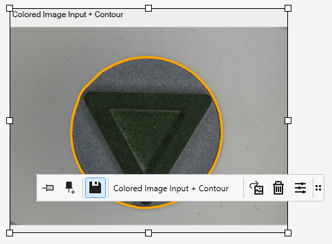
Click on an image in the Gallery to open the annotation popup.
| Pin function (time fixing): This function can be used to freeze an image to a specific point in time. If the image is “pinned”, it is no longer updated by successor data from the live analysis and remains unchanged even when scrolling through the timeline. For better orientation, the selected time is also visualized by a marking directly in the Analytics Timeline. |
| Pin & Copy: This function extends regular pinning by creating a copy of the current image and inserting it into the Gallery as a new, independent object. While the original view can still be updated live, the newly created image remains fixed to the selected time. This enables the simultaneous comparison of different analysis states within a gallery. |
| Persistent function: Controls whether image data remains available for the review in the timeline.
|
Name | The name assigned here is displayed directly above the image in the Gallery for quick identification. |
| Export: You can use this button and the submenu to export the selected image. Details on the options can be found in the following section. |
| Delete: Removes the currently selected image from the Gallery. |
| Adjustments: Opens the Toolbox for image editing. The available parameters are explained in detail below. |


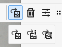


Image adjustments
The following illustration shows the available adjustments with which you can optimize the representation of an image to make details more visible.
 | These adjustments only affect the visual representation within the Gallery. They have no influence on the image data in the current analysis. The function is used to carry out tests quickly or to facilitate the placement of additional Toolboxes through improved visibility. |
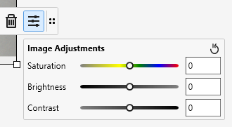
Saturation | Saturation: Adjusts the intensity of the colors. Increasing the color intensity makes the colors more vivid, while reducing the color intensity makes the image grayscale. |
Brightness | Brightness: Controls the general light intensity of the image. This can be used to brighten underexposed images or darken areas that are overexposed. |
Contrast | Contrast: Controls the difference between light and dark areas of the image. A higher contrast enhances the definition of details, while a lower contrast makes the image appear flatter. |
Export
Gallery items can be flexibly exported and saved locally. You have the choice of saving either individual images or entire groups. The export process can be started in two ways:
- Context menu in the Solution Explorer:
Right-click the desired item in the Solution Explorer. Several images can also be saved simultaneously via a multiselect in the Solution Explorer. - Annotation pop-up:
Use the export button directly within the image view.
A distinction is made between four options when exporting:
- Export Group
Exports the entire group including all contained items. The result corresponds to the resolution configured in the Gallery. - Export Original Image
Saves the original image in its full native resolution without additional overlays. - Export with Markups (full Resolution)
Saves the image in full resolution, whereby all annotations (markups) created are drawn directly into the image. - Export with Title
Saves the image together with the title and the line information below the representation. The resolution corresponds to the current display in the Gallery.