Creating the project examples
The TwinCAT project "Measuring"
Proceed as follows to create the Measuring project in TwinCAT:
- 1. Start Microsoft Visual Studio.
- 2. Select the menu command [File] → [New] → [Project…].
- 3. Select the TwinCAT Project from the Installed Templates list in the New Project dialog.
- 4. Define a name for the new project (e.g. Measuring)
- 5. Confirm the dialog with the [OK] button.
- An empty TwinCAT project is created and displayed.
The EAP device and a PLC project must now be created in the new project.
PLC Project Measuring
A PLC program is written within a TwinCAT PLC project. Create a PLC project by following these steps:
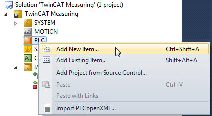
- 1. Right-click on the node PLC in your TwinCAT project and select the command [Add New Item…] (see figure above).
- The Add New Item dialog opens.
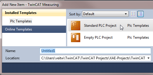
- 1. Select the Standard PLC Project template, define a name (in this case Measuring is recommended) and close the dialog with [Add].
- An empty Standard PLC Project is created.
A Standard PLC Project references several basic PLC libraries by default. The library Tc2_Utilities is also required for the sample program. Add a reference to this library as follows:
- 1. Right-click on the node References in the PLC project node (see figure).
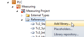
- 1. Select the command [Add Library…]
- The Add Library dialog opens.
- 2. Expand the Systems node and select the PLC library with the name Tc2_Utilities.
- 3. Confirm the dialog with [OK].
- The selected PLC library is shown in the list of references.
The "Measuring" PLC sample program
The Measuring sample program is intended to simulate a straightforward measurement for a product or workpiece with an identification number and make the data available later to another controller via EAP.
For this task a function block (FB) with the name GetMeasure is generated, which supplies randomly different measured values, and a MAIN program is written, which deals with the function of making the determined data available on request.
Function block GetMeasure
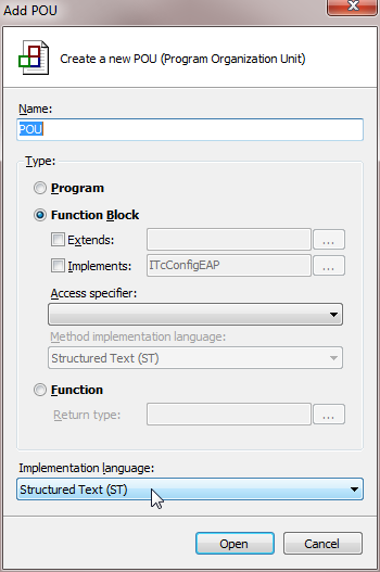
- 1. Right-click on the node POUs in the PLC project (see figure).
- The Add POU dialog opens.
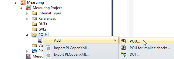
- 1. Enter GetMeasure as name, select Type: Function Block and Implementation Language: Structured Text (ST).
- After confirmation with [Open], the new function block is displayed in the editor, and the logic can be implemented.
The FB should have the following input parameters:
- NominalMeasure
A nominal value, which is normally expected for the product. - Variance
A value for the variance. The measured value simulation should subsequently return a value from the interval [nominal value – 0.5 * variance, nominal value + 0.5 * variance]. - Steps
Steps defines the step size with which the variance can occur.
The input parameters (NominalMeasure = 5000, Variance = 1000, Steps = 100) are therefore used to randomly generate a measured value [4500, 4600, 4700, …, 5400, 5500] to be returned as output parameter by the FB. The program code for the FB GetMeasure can then look as follows:
FUNCTION_BLOCK PUBLIC GetMeasure

VAR_INPUT
nominalMeasure : UDINT;
variance : UDINT;
steps : UINT;
END_VAR

VAR_OUTPUT
measure : UDINT;
END_VAR

VAR
FB_SystemTime : GETSYSTEMTIME;
currTimeLo : UDINT;
currTimeHi : UDINT;

FB_Randomizer : DRAND;
rand : LREAL;
seed : INT;

varianceEffective: UDINT;
varianceAbsolute : UDINT;
deviation : UDINT;
END_VAR

FB_SystemTime( timeLoDW => currTimeLo, timeHiDW => currTimeHi );
seed := UDINT_TO_INT(currTimeLo);
FB_Randomizer(Seed := seed, Num => rand);
varianceEffective := variance / steps;

varianceAbsolute := LREAL_TO_UINT(rand * UDINT_TO_LREAL(varianceEffective)) * steps;

IF varianceAbsolute >= (variance / 2) THEN
    deviation := varianceAbsolute - (variance / 2);
    measure := nominalMeasure + deviation;
ELSE
    deviation := (variance / 2) - varianceAbsolute;
    measure := nominalMeasure - deviation;
END_IF;
Copy the program code to FB GetMeasure. Then open the MAIN program by double-clicking in the editor. Here, the main program is now coded. An input variable and three output variables are defined in the main program.
The MAIN program:
Input variable:
- in_Req of type BOOL
is used to log a request from the other controller.
Output variables:
- out_Measure of type UDINT
should receive the measured value from the FB GetMeasure. - out_ProductID of type UDINT
should receive an identification number (ID), which identifies the product unambiguously. - out_Ack of type BOOL
should have the value FALSE, as long as no measurement result and no ID were written to the corresponding output variables.
PROGRAM MAIN
VAR
    in_Req AT%I* : BOOL := FALSE;

    out_Measure AT%Q* : UDINT := 0;
    out_ProductID AT%Q* : UDINT := 0;
    out_Ack AT%Q* : BOOL;

    request : BOOL := FALSE;
    isReady : BOOL;

    FB_R_TRIG : R_TRIG;
    FB_F_TRIG : F_TRIG;
    FB_GetMeasure : GETMEASURE;
    FB_TON : TON;
END_VAR

(*    START:     Detecting an incomming request
            to deliver the measure of the next product*)
    FB_R_TRIG( CLK := in_Req );
    IF FB_R_TRIG.Q THEN
        out_Ack := FALSE;
        request := TRUE;
    END_IF;

    FB_F_TRIG(     CLK := in_Req );
    IF FB_F_TRIG.Q THEN
        out_Ack := FALSE;
        request := FALSE;
    END_IF;
(*    END:     Detecting an incomming request*)

(*    START:     Simulating duration for measuring the next product*)
IF isReady THEN
    IF request THEN
        FB_GetMeasure(    nominalMeasure := 5000,
                        variance := 1000,
                        steps := 100,
                        measure => out_Measure );

        out_ProductID := out_ProductID + 1;
        request := FALSE;
        isReady := FALSE;
        out_Ack := TRUE;
    END_IF;
ELSE
    FB_TON( PT := T#200MS,
            IN := NOT FB_TON.Q );

    isReady := FB_TON.Q;
END_IF;
(* END: Simulating duration for measuring the next product*)- 1. Copy the program code for the main program to the program MAIN.
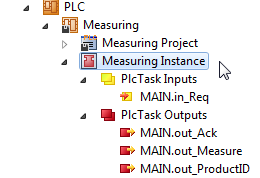
- 2. Compile the PLC project by clicking the menu entry [Build] → [Build Solution].
- An instance for the PLC project is created, in which the input and output variables for the PLC program can be found as process variables (see figure). These can later be linked in TwinCAT.
The EAP device
Finally, an EAP device under I/O configuration must be created in TwinCAT:
- 1. Expand the node I/O TwinCAT 3 and right-click on the node Device.
- 2. Select the entry [Add New Item…] in the context menu.
- The dialog Insert Device appears.
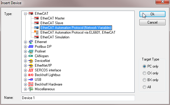
- 1. From the list select the type: EtherCAT Automation Protocol (Network Variables) which belongs to the EtherCAT devices and press [OK].
- 2. You may be asked to select an adapter, via which the EAP device should communicate.
- The EAP device is then created and preconfigured with default settings.
The EAP device now has to be linked to a cyclic task, so that it can send and receive variables in a real-time context.
- 3. Right-click on the EAP device and select the menu entry [Add New Item…].
- The Insert Box dialog opens.
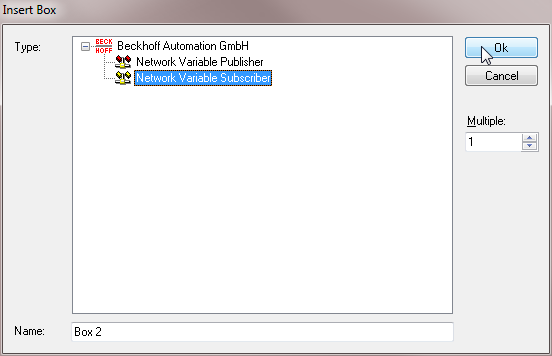
- 1. Select Network Variable Subscriber and press [OK].
- A Box 1 (Subscriber) is created below the EAP device.
- 2. Right-click on this new node and again select the menu entry [Add New Item…].
- The dialog Import Network Variable is displayed.
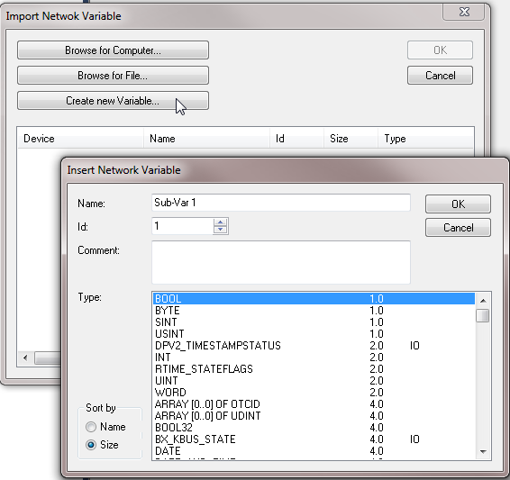
- 1. Press [Create new Variable…].
- The dialog Insert Network Variable opens (see figure above).
- 2. Select BOOL from the list data types, then press [OK].
- The Subscriber variable Sub-Var 1 is added below the Subscriber node.
- 3. Expand Sub-Var 1 and the Inputs node below.
- 4. Right-click the node VarData and select the entry [Change Link…] from the context menu.
- The dialog Attach Variable is displayed.
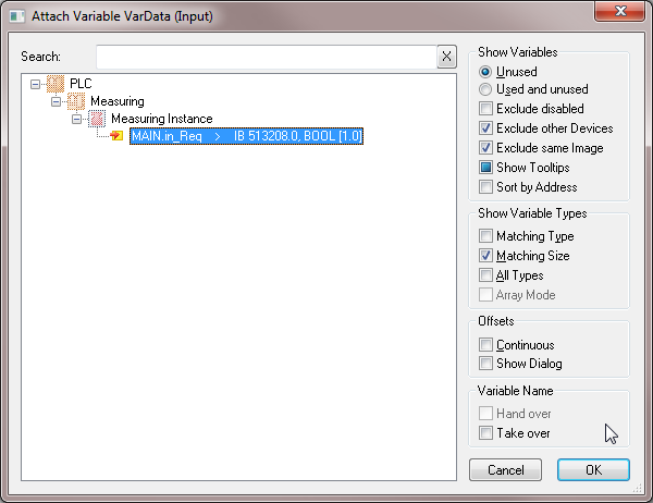
- 1. Select the PLC variable MAIN.in_Req and press [OK].
- The variable is then linked, and the project configuration is complete.
Activate your TwinCAT project, so that subsequently a link with the EAP device can be created with the TwinCAT EAP Configurator.
The TwinCAT project "Operating"
The TwinCAT project Operating is created in the same way as the TwinCAT project Measuring. Therefore, only the few differences and the program code for the PLC project are explained.
The Operating PLC sample program
The Operating sample program is intended to simulate a machining operation for a product or workpiece with an identification number in a simple manner. After machining is complete, it should be able to notify another controller via EAP that the next workpiece can be machined.
For this task a function block (FB) with the name Processing is created, which simulates the machining duration, which depends on an input parameter (the measured value for this workpiece). The MAIN program issues a request for the next workpiece, once the last machining operation is complete and logs the confirmation of the request, so that machining of the next workpiece can begin.
Processing function block
The FB should have the following input parameters:
- measure
The value that has been measured for the workpiece to be machined.
The FB simulates a processing duration by halving the value of the input parameter and waiting in seconds. During this waiting time the output parameter busy is set to TRUE, otherwise the value is FALSE. The program code for the FB Processing can then look as follows:
FUNCTION_BLOCK PUBLIC Processing

VAR_INPUT
    measure : UDINT := 0;
END_VAR

VAR_OUTPUT
    bBusy : BOOL := FALSE;
END_VAR

VAR
    FB_TON : TON;
    bReady : BOOL;
    processingTime : TIME;
END_VAR

processingTime := UDINT_TO_TIME(measure/2);

FB_TON.PT := processingTime;
FB_TON.IN := NOT FB_TON.Q;
FB_TON();

bBusy := NOT FB_TON.Q;- 1. Copy the program code to FB Processing.
- 2. Open the program MAIN by double-clicking in the editor.
- Here, the main program is now coded. Three input variables and an output variable are defined in the main program.
The MAIN program:
Input variables:
- in_Measure of type UDINT
should receive the measured value from project Measuring. - in_ProductID of type UDINT
should be assigned an identification number (ID), which identifies the product unambiguously and is communicated by the project Measuring. - in_Ack of type BOOL
should receive the value FALSE from project Measuring, as long as the next workpiece has not yet been measured, i.e. is not yet available for machining.
Output variable:
- out_Req of type BOOL
is used to request the next workpiece from the other controller.
PROGRAM MAIN

VAR
    in_Measure AT%I* : UDINT := 0;
    in_ProductID AT%I* : UDINT := 0;
    in_Ack         AT%I* : BOOL := FALSE;

    out_Req AT%Q* : BOOL := FALSE;

    acknowledge : BOOL := FALSE;
    proceeding : UDINT := 0;

    FB_R_TRIG : R_TRIG;
    FB_F_TRIG : F_TRIG;
    FB_Processing : Processing;
END_VAR

(*    START:     Detecting an incomming acknowledge
            to operating the next product*)
    FB_R_TRIG( CLK := in_Ack );
    IF FB_R_TRIG.Q THEN
        acknowledge := TRUE;
    END_IF;

    FB_F_TRIG( CLK := in_Ack );
    IF FB_F_TRIG.Q THEN
        acknowledge := FALSE;
    END_IF;
(*    END:     Detecting an incomming acknowledge*)

(*    START:     Simulating duration of operating the next product*)
IF FB_Processing.bBusy THEN
    FB_Processing();
ELSE
    IF acknowledge THEN
        acknowledge := FALSE;
        out_Req := FALSE;
        proceeding := in_ProductID;
        FB_Processing(measure := in_Measure);
    ELSE
        proceeding := 0;
        out_Req := TRUE;
    END_IF;
END_IF;
(* END: Simulating duration of operating the next product*)- 1. Copy the program code for the main program to the MAIN program.
- 2. Compile the PLC project by clicking the menu entry [Build] → [Build Solution].
- The project is then compiled.
The EAP device
In the EAP device, for this project a Publisher with a Publisher variable of data type BOOL is added, instead of a Subscriber. This variable is then linked with the PLC variable MAIN.out_Req.
Activate this TwinCAT project, so that subsequently a link with the EAP device can be created with the TwinCAT EAP Configurator.