Interaction with the graphical user interface (GUI)
EAP devices are configured via the graphical user interface and the Toolbox. The Toolbox can be found in section EapLanguage (see illustration). It contains the tools required for a configuration.
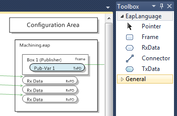
The Frame, TxData and RxData tools are handled in the same way.
- 1. Left-click on one of the tools.
- 2. Pull the mouse pointer to the position at which the new element is to be generated.
The required element cannot be generated at the current position while the mouse pointer shows a prohibited action symbol (red circle with a diagonal line) . Otherwise the mouse pointer changes to the symbol for the respective tool.
 - 3. Press the left mouse button again.
- The new element is added, and the standard tool (Pointer) becomes active again.
 | Pasting several elements of one type To generate several elements of one type, the tool can be selected with a double-click. In this case the selected tool remains active after the element has been inserted, until the right mouse button is pressed, for example. |
The Pointer tool
The standard tool is the Pointer  . This is usually enabled. If another tool was enabled and the ESC key or the right mouse button is pressed later, the Pointer tool becomes active again.
The Pointer tool can be used to select individual objects, e.g. in order to view their properties in the Properties window. In addition, the EAP device object can be moved vertically within the Configuration Area. A double-click can be used to bring another EAP device object from the Publisher/Subscriber Area into the Configuration Area. In addition, the names of the elements of an EAP device object can be selected and modified by double-clicking.
Right-clicking on one of the elements opens a context menu listing some commands that can be executed on the respective element. The standard commands [Cut], [Copy], [Paste] and [Delete] are generally supported for all elements. They can be used to cut, copy, paste or delete elements, as usual for many other applications.
The [Properties] command opens the Properties window, in which the configuration properties of the respective element can be found.
The Frame tool
The Frame tool  is used to generate a new TxFrame element within an EAP device object. Frame elements can only be generated within the box of an EAP device object that is located within the Publisher Area or the Configuration Area.
The TxData tool
Within a TxFrame, TxData elements are then added with the aid of the TxData tool  . TxData elements cannot be generated anywhere else.
In addition to the standard commands, the context menu for the TxData element contains the command [Process Data Configuration]. The command opens a dialog for generating and editing TxPDO elements. One of the TxPDOs can then be selected for the TxData. A more detailed description of the dialog can be found in section Generating a communication link manually.
The RxData tool
The RxData tool  is used to generate a new RxData element within an EAP device object. RxData elements can only be generated within the box of an EAP device object that is located within the Subscriber Area or the Configuration Area.
Like for TxData elements, in addition to the standard commands, the context menu for the RxData element contains the command [Process Data Configuration], which can be used to generate and edit RxPDO elements, and to assign them to the RxData (cf. section Generating a communication link manually).
The Connector tool
The Connector tool  is a wizard, used for semi-automatic configuration of a communication link between two EAP device objects. Two application cases are supported: TxData to RxData and EAP device object to EAP device object.
TxData to RxData
The first case relates to the application of a Connector between TxData and RxData. For this action the properties of the respective Publisher and Subscriber elements are adjusted such that a communication link is created.
- 1. Select the Connector tool.
- 2. Drag the mouse pointer to the required TxData element.
- 3. Press the left mouse button.
- 4. Drag the mouse pointer to the required RxData element.
- 5. Press the left mouse button again.
- The following dialog opens.
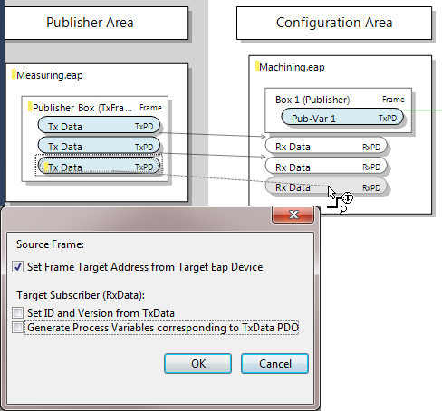
It lists three options which can be set as required, and depending on the current configuration status:
- Set Frame Target Address from Target EAP Device.
This option is enabled by default. In this case, the AMS NetID of the target EAP device is entered as destination address during automatic generation of the TxFrame. - Set ID and Version from TxData.
This option ensures that the identification number and the version number of the selected TxData element are adopted during configuration of the RxData Subscriber element. If these two properties do not match, a communication link cannot be established. - Generate Process Variables corresponding to TxData PDO.
This option is only available if a TxPDO has already been defined and configured on the Publisher side for the TxData. Ideally, the TxPDO should already have the full list of references for the required Tx variables. This ensures that the whole RxPDO including all required Rx variables is created and configured on the receiving side. Accordingly, the communication link is then also configured correctly.
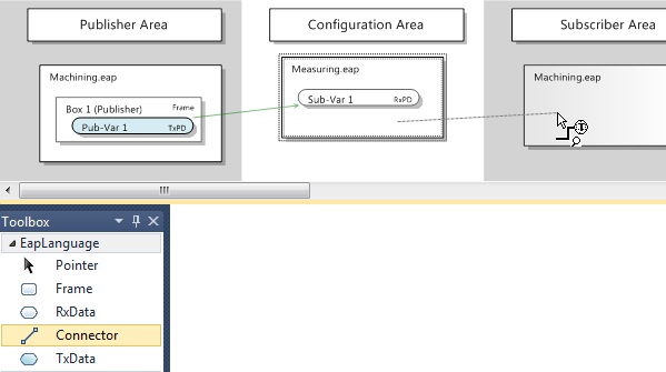
EAP device object to EAP device object
The second case is the use of a Connector between two EAP device objects. With this action, a Publisher with all the nested elements it requires is created and preconfigured for the EAP device object with the starting point of the Connector. For the EAP device object with the end point of the Connector, a Subscriber with all the nested elements it requires is created and preconfigured according to the previously created Publisher, so that a valid communication link is available.
- 1. Select the Connector tool.
- 2. Drag the mouse pointer to the free area of an EAP device object, which is to act as Publisher.
- 3. Press the left mouse button.
- 4. Drag the cursor to a free area in the required target EAP device object.
- 5. Press the left mouse button again.
- The following dialog opens.
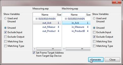
The dialog is divided into two halves. In the left half, a list box shows all symbol names of process variables whose data can be sent with the aid of the EAP device. The process variables may originate from a PLC program of the machine on which the EAP device was instantiated, for example.
In the right half, the symbol names of the process variables of the target machine are listed, to which the target EAP device can write the received data. If no symbol names are listed, no communication link can be generated.
The dialog offers several filter options for the symbol table. One option is to display all available symbol names: either symbols that have already been used, together with unused symbols (Used and Unused); or only symbols that have not yet been used (Unused).
In addition, you can select whether only the symbols for the input variables should be listed (Exclude Output enabled) or only the symbols for the output variables (Exclude Input enabled) or both (neither Exclude Input nor Exclude Output enabled). By default only the symbols for the output variables are shown on the left (for the EAP Publisher) and only the symbols for the input variables on the right (for the EAP Subscriber).
If a symbol from one of the two lists has been selected, the two filter options Matching Size and Matching Type can be used in a meaningful way. If, for example, the symbol for a process variable was selected on the left for the EAP Publisher, the symbol name list for the EAP Subscriber on the right can be filtered such that only the symbol names of the process variables are listed,
- with a Matching Size
(the data type has the same size as the data type of the Publisher process variable); - with a Matching Type
(the data type is the same as the data type of the Publisher process variable); - or with a Matching Size and a Matching Type
(both properties match).
Finally, there is the option Set Frame Target address from Target EAP Device. This option is enabled by default. In this case, the AMS NetID of the target EAP device is entered as destination address during automatic generation of the TxFrame.
The EAP device object
Via its context menu, the EAP device object offers various functions that enable reading and writing, generating and deleting, importing and exporting of a configuration. In this way, a communication link between two EAP device objects can be configured manually without using the Connector tool, for example.
Generating a communication link manually
The ideal approach to generating a communication link between two EAP device objects manually is to generate and configure the variables and process data objects (PDOs) first (See sections Generating variables and Generating process data objects). A Tx/Rx PDO then represents a data unit, for which send and receive characteristics can be configured with the aid of a TxData and TxFrame or an RxData element. Once the required PDOs have been created, the required TxFrames, TxData and RxData can be created (cf. sections The Frame tool, The TxData tool and The RxData tool) and fully configured (cf. sections The Frame, The TxData and The RxData).
Import/Export
The configuration of an EAP device can be exported to an XML-based file via the command [Export EAP Device Config File]. This file is therefore referred to as EAP Device Configuration (EDC). A TwinCAT EAP device that was created and configured with TwinCAT 3 also offers a function for exporting its configuration to an EDC file. The TwinCAT EAP Configurator can then read this file via the import function [Import EAP Device Config File]. On import of an EDC file the existing configuration is discarded and is therefore lost, if it was not backed up.
In addition to the EAP configuration, an EDC file exported from TwinCAT 3 also contains the symbol information for all PLC programs created in the TwinCAT project. After import of the EDC file into the TwinCAT EAP Configurator, this symbol information is available for creating communication links.
Reading an active device configuration
The command [Read from Device] from the context menu of the EAP device object reads the current device configuration of a TwinCAT EAP device. Three conditions must be met:
- The TwinCAT EAP device must be active.
- An ADS/AMS route must be entered from the PC on which the TwinCAT EAP Configurator runs to the PC on which the TwinCAT EAP device runs.
- The Local AoE Net ID must be entered correctly in the TwinCAT EAP Configurator under the EAP device properties.
An TwinCAT EAP device only becomes active once it was configured and activated via TwinCAT 3. If one of these prerequisites is not met, the TwinCAT EAP Configurator cannot communicate with the EAP device. Once the current EAP configuration has been read, it is visualized directly.
| The current device configuration is discarded. When a device configuration is read, the existing configuration is discarded and is therefore lost, if it was not backed up. |
Writing a new device configuration
One of the main functions provided by the TwinCAT EAP Configurator is writing of a device configuration. The convenient option to generate and modify an EAP configuration with the aid of the TwinCAT EAP Configurator leads to the need to transfer this configuration to a TwinCAT EAP device. In addition to the prerequisites for reading an EAP configuration, a further requirement must be satisfied for reading.
Before a configuration can be transferred to a TwinCAT EAP device, the device must be set to a suitable state, in which changing the configuration is uncritical. The TwinCAT EAP device features a state machine with four states.
- Init (INIT)
The TwinCAT EAP device is never in INIT state, except for a short time during activation of the TwinCAT project. In this case the EAP device was already instantiated, but not yet configured. - Pre-Operational (PREOP)
In PREOP state the TwinCAT EAP device is fully preconfigured, so that cyclic processing of the process data is ready to commence. In PREOP state further configurations can be implemented in the TwinCAT EAP device, e.g. with the aid of the TwinCAT EAP Configurator. - Safe-Operational (SAFEOP)
When the EAP device switches from PREOP state to SAFEOP state, the current configuration is checked for consistency, references between objects defined via the configuration are created, and links to the PLC variables are created based on the configured symbol names. In SAFEOP state the EAP device already sends variables, but it does not yet receive data. - Operational (OP)
In OP state, the EAP device receives and sends the configured process data cyclically and highly deterministically.
Before the new device configuration can be written, the TwinCAT EAP device must be switched to PREOP state. The state can be switched using the icon bar in the EAP Config Tool Window (see section Displaying the object dictionary).
A device configuration can be written in two ways:
- Write All to Device
The command [Write All to Device] transfers all configuration data relating to the EAP device object in the TwinCAT EAP Configurator to the TwinCAT EAP device. All these configuration data are grouped with the aid of the object dictionary (cf. section The object dictionary). The command [Write All to Device] can also be called up from the icon bar .
. - Write Changes to Device
The command [Write Changes to Device] it used to selectively transfer those configuration data to the TwinCAT EAP device, which were modified with the aid of the TwinCAT EAP Configurator. The modifications are indicated with a yellow marker, which is displayed in the object dictionary and in the graphical interface. The object dictionary contains detailed information on which entries were modified. The command [Write Changes to Device] can also be called up from the icon bar .
.
Once the transfer is complete, the marking for the successfully written configuration data changes to green. Any configuration data for which the transfer failed are marked in red.
Displaying the object dictionary
All configuration data relating to the EAP device object in the TwinCAT EAP Configurator are grouped with the aid of the object dictionary. This object dictionary can be displayed in tabular form by selecting the command [Show in Tool window] from the context menu of the EAP device object (see illustration). Up to four of these Tool windows are supported, so that the object dictionaries of up to four different EAP devices can be viewed at the same time.
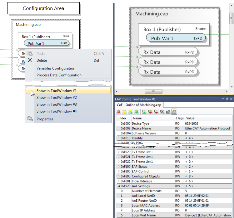
At the top of the Config Tool window, the file name of the corresponding EAP device object is displayed, and an icon bar below, which can be used to execute several commands (see illustration above), as explained below.
Set EAP Device State
The first four icons can be used to change the state of the TwinCAT EAP device. Each of the four states of the EAP state machine has an icon.
|
1. |
Icon |
|
Switches the EAP device to INIT (1) |
|
2. |
Icon |
|
Switches the EAP device to PREOP (2) |
|
3. |
Icon |
|
Switches the EAP device to SAFEOP (4) |
|
4. |
Icon |
|
Switches the EAP device to OP (8) |


Read from Device
The icon  executes the command [Read from Device] as described in section Reading an active device configuration.
Write Changes to Device
The icon executes the command [Write Changes to Device], as described in section Writing a new device configuration.
Write All to Device
The icon executes the command [Write All to Device], as described in section Writing a new device configuration.
Clear Object Dictionary
The icon  executes the command [Clear Object Dictionary], as described in section Deleting the configuration.
Clear Change Flags
The icon  executes the command [Clear Change Flags], as described in section Configuration state display.
Compare to Online Data
The icon  can be used to add a further column to the object dictionary, in which the configuration data of the currently active TwinCAT EAP device are displayed. The icon works like a toggle switch, i.e. the column appears when the icon is clicked for the first time and is hidden when it is clicked again. Whenever the column display is enabled, the configuration data are read from the TwinCAT EAP device again and displayed.
Deleting the configuration
The configuration can be deleted via the command [Clear Object Dictionary] from the context menu of the EAP device object. A configuration can be deleted separately for each EAP device object. All objects (except a few) are deleted from the object dictionary of the respective EAP device object, so that the configuration is empty. The objects that are not deleted are standard objects, which are part of every EAP device and therefore cannot be deleted. They include the status of the EAP devices and the destination address such as MAC, IP and AMS NetID. This information is required by the TwinCAT EAP Configurator, for example, in order to be able to communicate properly with the TwinCAT EAP device.
The objects that can be deleted are the dynamic objects generated while new elements such as TxFrame, Tx/Rx data, Tx/Rx PDOs or Tx/Rx variables are created.
Configuration state display
The TwinCAT EAP Configurator executes various tasks on the configuration data of the EAP device objects. Some of these tasks are indicated in the graphical interface and in the tabular display of the object dictionary through colored flags. This flag indicates the configuration state and has the following meaning:
|
Highlighting |
Meaning |
|---|---|
|
none |
No flag is used in the following cases:
|
|
yellow |
The configuration data have changed. |
|
green |
The configuration data were written successfully. |
|
red |
Writing of the configuration data has failed. |
The flag can be reset with the command [Clear Change Flags] from the context menu of the EAP device.
The graphical user interface
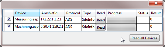
The context menu of the graphical user interface itself offers two further important commands: [Read All Devices] and [Write All Devices]. Clicking on one of these commands opens a tabular dialog, in which all EAP device objects are listed line-by-line, which were created in the TwinCAT EAP Configurator project (see illustration).
Read All Devices
The dialog in the upper illustration shows a tabular list of all EAP device objects in the project. In addition to a checkbox and a button for each row, the following information is displayed in the table columns:
- The file name of the EAP device object
- The AMS NetID entered in the EAP device object
- The communication protocol for device configuration
- A progress indicator
- A status indicator
- A results display
The dialog can be used to read the configurations of all listed EAP devices, provided the basic requirements are met (cf. section Reading an active device configuration f.). Three options are available:
I. Read configuration of all listed EAP devices
- All checkboxes must be ticked. This is the default state when the dialog opens.
- 1. Click on [Read all Devices] button
- All EAP device configurations are read.
II. Read configuration of a particular EAP device
- 1. Click on the [Read] button in the row in which the required EAP device is listed.
- Only the configuration of the selected EAP device is read.
III. Read configuration of selected EAP devices
- 1. Select EAP devices whose configuration you want to read by ticking the respective boxes
- 2. Click on [Read all Devices] button.
- The configurations of the selected EAP devices are read
Write All Devices
The process of writing the configurations to all EAP devices is analogous to the read process (see previous section).
Select protocol (ADS, UDP)
In the Protocol column, for each listed EAP device object the protocol to be used for configuring the respective EAP device can be selected. ADS and UDP are available. UDP means that the application protocol AoE via UDP is used automatically (cf. The functional principle of the TwinCAT EAP Configurator).
| EAP Configurator tool and TwinCAT EAP device on the same computer If the EAP Configurator tool and the TwinCAT EAP device are executed on the same computer, only the ADS/AMS protocol can be used for the configuration. The AoE protocol does not work in this configuration, because a TwinCAT EAP device invariably receives and sends AoE packets directly via TwinCat’s real-time capable network card driver. Therefore, it is not possible to transfer AoE packets between the EAP Configurator tool and the TwinCAT EAP device within the PC. Only ADS/AMS communication can be used within the PC. With this communication type, the TwinCAT router can relay ADS/AMS packets to receivers within the PC. |
Progress indicator
The progress indicator provides an overview of the time taken by the reading/writing of the configuration of each EAP device object and indicates when the write or read operation is complete.
Status and result
After writing or reading of the configuration, the Status column indicates whether the process is complete and whether errors occurred.
The Result column shows either 0, if no error has occurred, or an error code.