Overview
TE1400 TwinCAT Target for Simulink®
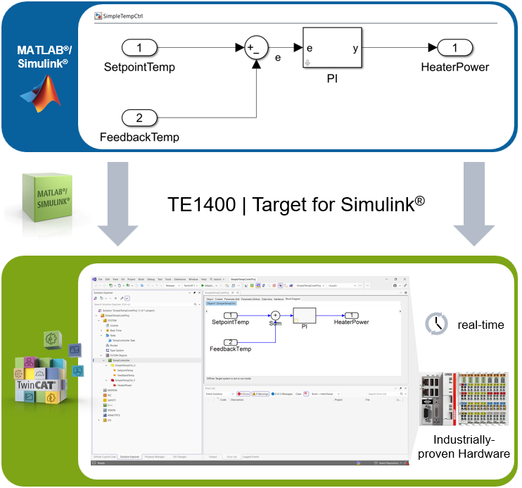
With the TwinCAT 3 Target for Simulink® it is possible to make models developed in Simulink® usable in TwinCAT 3. Various toolboxes such as SimScape™ or Stateflow™ or DSP System Toolbox™ can be integrated in Simulink®. Embedded MATLAB® function blocks are also supported. The models are automatically compiled in C/C++ code with the aid of the Simulink® Coder™ and transformed into TwinCAT objects with TwinCAT 3 Target for Simulink®. These TwinCAT objects can then be executed in real-time in the TwinCAT runtime. They can be either TcCOM objects for direct instantiation and linking with real-time tasks or function blocks for instantiation and processing in a PLC project.
Areas of application and application examples
The areas of application of TwinCAT Target for Simulink® can be summarized by the following keywords:
- Rapid Control Prototyping
- Real-time simulation
- SiL (Software in the Loop) simulation
- HiL (Hardware in the Loop) simulation
- Model-based design
- Model-based monitoring
The following application examples are intended to illustrate possible areas of application:
- Example 1: Rapid Control Prototyping
During the simulation development stage in Simulink®, a controller is implemented as a Simulink® model, which is integrated into the simulation model of the control loop via Model Referencing. This enables the closed control loop to be designed and tested in a simulation (Model in the Loop simulation (MiL)). The controller model is then compiled unchanged into a TwinCAT module via mouse click, which then operates as real-time controller for an actual system. Since standard Simulink® function blocks are used as inputs and outputs, they can be used in the higher-level Simulink® model as well as in the module generated later in TwinCAT. - Example 1a: Real-time simulation of a controlled system
The controlled system is also implemented as a Simulink® model, which is integrated into the model of the closed control loop via Model Referencing. The TcCOM module generated from this is used to perform a real-time simulation, in which a controller implemented in IEC61131-3, C++ or Simulink® can be tested. - Example 2: Real-time simulation of a machine/virtual commissioning
A TcCOM module is generated from a machine model created in Simulink®. This can be used to test a PLC program in real-time, before the actual machine is connected (virtual commissioning). Depending on the configuration, SiL or HiL simulations can be performed in this way. See also TE1111 EtherCAT Simulation. - Example 2a: SiL simulation of system components
According to VDI/VDE 3693 Part 1, software-in-the-loop (SiL) is defined as a stage following an MiL simulation, in which the control code is available as series code. The series code can be executed in an emulated controller, for testing against a system simulation model.
According to this definition, there are three options for a SiL simulation of systems (components) with TwinCAT: - Using the TE1421 Simulation Runtime for FMI, a TwinCAT 3 configuration is exported as a Functional Mock-up Unit (FMU) and integrated into Simulink® via the FMU import feature. The serial code runs on the emulated controller and communicates directly with the system model in Simulink® in a synchronized manner.
- The system model remains in Simulink® and uses ADS to communicate with the series code, which is executed in the TwinCAT runtime. See also TE1410 interface for MATLAB® and Simulink®.
- The system model is also compiled into a TcCOM module and executed in real-time (see example 1a).
- Example 2b: HiL simulation of system components
According to VDI/VDE 3693 Part 1, hardware-in-the-loop (HiL) is defined as an advanced testing stage, in which the actual target control code is tested on an actual controller against a system model. The latter is executed in a simulation tool, which acts as a bus device and therefore uses the actual communication networks of the automation system for communication with the actual controller.
Based on this definition, the model of the system or the system components is converted to TcCOM modules and executed on a second industrial PC, taking into account the real-time requirements. The function TE1111 EtherCAT Simulation is used to configure this IPC such that it makes the mirrored process image available to the actual controller. In this way, it is possible to use the actual controller and the actual configuration to communicate with the “simulation IPC” in hard real time. - Example 3: Model-based monitoring of system components
In many cases, measured variables are of interest that are not directly accessible or would result in excessive effort/costs. By using a physically representative model with measurable input variables, non-measurable variables can still be determined. An example is temperature measurement at locations that are inaccessible, such as the permanent magnet temperature in an electric motor. Based on a thermal model of the motor, the temperature can be estimated by means of secondary parameters such as electric current, rotational speed and cooling temperature.
Typical procedure
The basic workflow with the TE1400 is as follows:
- Models are developed in Simulink®.
- Simulink® Coder™ automatically compiles these functions into C/C++ code.
- TwinCAT 3 Target for Simulink® converts the generated code into TwinCAT objects.
- The generated modules are integrated into a project in TwinCAT 3 Engineering.
- They are then transferred to the TwinCAT 3 runtime as part of the TwinCAT project and executed there in the real-time environment.
Integration methods in TwinCAT 3 Engineering
Depending on the use case, the generated modules can be integrated into the project in different ways:
- TcCOM object: suitable when the generated module is to be integrated into the TwinCAT runtime as a standalone TwinCAT component.
- PLC function block: suitable when the generated module is to be used directly from within PLC code and integrated into existing PLC flow logic.
- TcCOM Wrapper FB: suitable for establishing a connection between both of the aforementioned methods. The TcCOM object can be called from the PLC in this way while remaining a standalone object in the TwinCAT project tree.
All methods can be seamlessly integrated into TwinCAT 3 Engineering and combined with other TwinCAT functions.
Further Information
Technical short videos
Product descriptions
Customer application videos
Website for MATLAB® and Simulink® with TwinCAT 3: https://www.beckhoff.com/matlab