Bode Plot - Set properties
A Bode Plot can contain three different types of sets (characteristic curves). Record sets for displaying the result of a recording, Filter sets for assessing the characteristic curve of a filter and Result sets for combining two already existing sets.
Some settings concern all sets, some are specialized.
Appearance
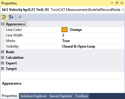
The settings in the Appearance category are available for all sets.
- Line Colors: Indicates the color of the set (characteristic curves and icon in Solution Explorer).
- Line Width: Sets the line width of the set in the Bode Plot Editor.
- Marks: Indicates whether the interpolation points of the characteristic curve should be displayed.
- Visibility: Indicates which variants of the characteristic curves should be displayed. The following values and their combinations are available:
- Open Loop: Frequency response of the open control loop.
- Closed Loop: Frequency response of the closed control loop.
- Process: Frequency response of the link.
Record Set
In the settings for the record set, you can see the configuration with which the recording took place. Therefore, the same values exist here that are already described in the plot.
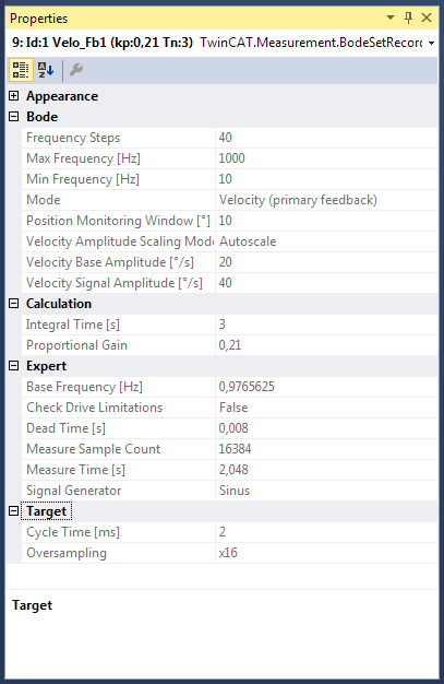
Bode
Under this category all settings are summarized in order to configure a new Bode Plot.
- Frequency Steps: Number of interpolation points in the Bode Plot.
- Max Frequency [Hz]: Indicates the upper frequency limit of the Bode Plot [in Hz].
- Min Frequency [Hz]: Indicates the lower frequency limit of the Bode Plot [in Hz].
- Mode: Sets the Bode Plot mode. The following are available
- Torque: Executes a Bode Plot for the torque (or current) interface. (AX5000 only)
- Velocity (primary feedback): Executes a Bode Plot for the velocity interface. The actual values of the primary encoder are used for this. (AX5000 only)
- Velocity (dp/dt directly from primary feedback): Executes a Bode Plot for the velocity interface. (AX5000 only)
- Velocity (secondary feedback): Executes a Bode Plot for the velocity interface. The actual values of the secondary (external) encoder are used for this. (AX5000 only)
- Position (NC interface without oversampling): Executes a Bode Plot for the position.
- Velocity (NC interface without oversampling): Executes a Bode Plot for the velocity.
- Torque (NC interface without oversampling): Executes a Bode Plot for the torque (or current).
The following settings are shown or hidden, depending on the mode:
- Position Monitoring Window [°]: Defines a window that is monitored during the Bode plot. The object must not leave this window. The unit actually set is read out and the number is interpreted in accordance with the unit.
- Position Signal Amplitude [°]: The amplitude of the excitation is set here.
- Velocity Amplitude Scaling Mode: Scales the signal amplitude during the recording so as not to require excessively large movements as the frequency increases. The following are available:
- Constant: The amplitude corresponds to the parameterized signal amplitude and remains constant over the entire frequency range.
- 1 / X at 1000Hz: Scales the amplitude so that at 1000 Hz it has fallen to 1/X of the start amplitude at 1 Hz (~1/f). Useful ratios in practice are 1/5, 1/10 and 1/20.
- Torque Amplitude Offset: Specifies an offset for the torque amplitude [in %].
- Torque Amplitude Scaling Mode: Scales the signal amplitude during the recording, depending on the current frequency. The following are available:
- Autoscale: Scales the amplitude so that it is somewhat higher than the noise at a standstill.
- Constant: The signal amplitude remains the same over the entire frequency range. The amplitude 100 means 100 % of the maximum current.
- Torque Signal Amplitude: Sets the amplitude of the signal (or measuring) oscillation at 1 Hz (cf. Torque Amplitude Scaling Mode). The unit of measurement is to be taken from the system settings (e.g. Drive, NC, etc.) and cannot be specified here.
- Velocity Base Amplitude: Sets the amplitude of the basic oscillation (~1 Hz) for overcoming the static friction. The unit of measurement is to be taken from the system settings (e.g. Drive, NC, etc.) and cannot be specified here.
- Velocity Signal Amplitude: Sets the amplitude of the signal (or measuring) oscillation at 1 Hz (cf. Velocity Amplitude Scaling Mode). The unit of measurement is to be taken from the system settings (e.g. Drive, NC, etc.) and cannot be specified here.
Calculation
- Integral Time [s]: This is read during the plot. It is the integral time of the controller that is set on the drive.
- Proportional Gain: A desired performance can be achieved with the proportional gain.
Expert
- Base Frequency: Shows the frequency [in Hz] of the basic oscillation for overcoming the static friction (in the velocity modes only).
- Check Drive Limitations: If a check of the drive is to take place, this can be specified here.
- Dead Time [s]: Indicates the complete dead time in seconds.
- Measur Sample Count: Indicates the number of setpoint values and actual values from which an interpolation value of the Bode characteristic curve (a frequency point) is calculated.
- Measure Time: Indicates the length of time [in s] for which the system is excited with one frequency.
- Signal Generator: Indicates the curve type of the signal generator used.
Target
- Cycle Time: Indicates the last-used cycle time [in ms].
- Oversampling: Indicates the oversampling factor to be used. If set to Suggested, the highest useful factor is automatically selected when starting the recording.
Filter Set
The special settings for filter sets are represented as follows:
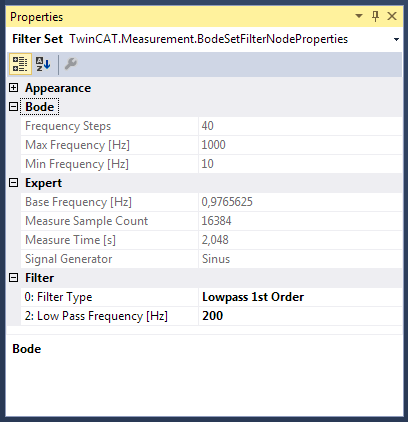
- Filter Type: The type of filter can be set here. The other properties can be edited, depending on the selection. The following are available:
- Lowpass 1st Order: First order low-pass.
- Lowpass 2nd Order: Second order low-pass
- Phase Correction 1st Order: First order phase correction link.
- Phase Correction 2nd Order: Second order phase correction link.
- Notch: Notch filter.
- High Pass Damping: High-pass damping factor.
- High Pass Frequency: High-pass frequency [in Hz].
- Low Pass Damping: Low-pass damping factor.
- Low Pass Frequency: Low-pass frequency [in Hz].
Result Set
In order to obtain the overlapping of two already existing sets, they must be specified in the settings for the result set.
Upon selecting the field, a list of possible sets is displayed.
The resulting characteristic curve is automatically determined from the two sets if the number and position of the interpolation points correlate. If one of the two source sets changes, then the result set is also re-calculated.
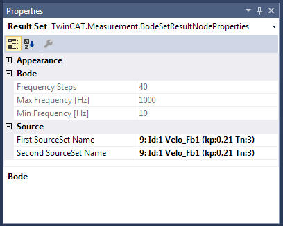
Source
- First SourceSet Name: Name of the first source set.
- Second SourceSet Name: Name of the second source set.