Bode Plot - Plot properties
All settings for a Bode Plot can be executed here. The following description refers to the representation in categories (switchable in the Properties toolbar).
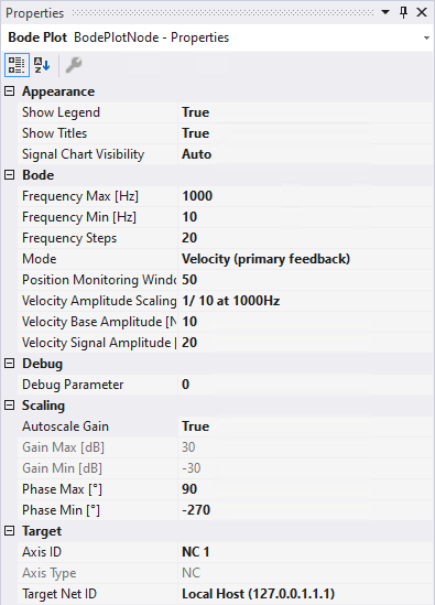
Appearance
- Show Legend: Indicates whether the legend should be shown in the footer of the Bode Plot editor.
- Show Titles: Indicates whether the headings of the charts should be shown in the Bode Plot editor.
- Signal Chart Visibility: Indicates whether the chart with setpoint and actual values of the recording should be shown or hidden. If Auto is set, the chart is only shown during a running recording.
Bode
All settings are summarized under this category in order to configure a new Bode Plot.
- Frequency Max: indicates the upper frequency limit of the Bode Plot [in Hz].
- Frequency Min: indicates the lower frequency limit of the Bode Plot [in Hz].
- Frequency Steps: indicates the number of measuring points in the Bode Plot.
- Mode: sets the Bode Plot mode. The following are available:
- Torque: executes a Bode Plot for the torque (or current) interface. (AX5000 only)
- Velocity (primary feedback): executes a Bode Plot for the velocity interface. The actual values of the primary encoder are used for this. (AX5000 only)
- Velocity (dp/dt directly from primary feedback): executes a Bode Plot for the velocity interface. (AX5000 only)
- Velocity (secondary feedback): executes a Bode Plot for the velocity interface. The actual values of the secondary (external) encoder are used for this. (AX5000 only)
- Position (without oversampling): executes a Bode Plot for the position.
- Velocity NC (without oversampling): executes a Bode Plot for the velocity.
- Velocity DRIVE (without oversampling): executes a Bode Plot for the velocity.
- Torque (without oversampling): executes a Bode Plot for the torque (or current).
- Position (primary feedback): executes a Bode Plot for the position. This mode is only available when an XPlanar mover is selected.
The following settings are shown or hidden, depending on the mode.
- Position Monitoring Window [°]: defines a window that is monitored during the Bode Plot. The object must not leave this window. The unit actually set is read out and the number is interpreted in accordance with the unit.
- Position Signal Amplitude [°]: this is where you set the amplitude of the excitation signal.
- Velocity Amplitude Scaling Mode: scales the signal amplitude during recording so that movements are not too large as the frequency increases. The following are available:
- Constant: the amplitude corresponds to the parameterized signal amplitude and remains constant over the entire frequency range.
- 1 / X at 1000Hz: scales the amplitude so that at 1000 Hz it has fallen to 1 / X of the start amplitude of 1 Hz (~1/f). Useful ratios in practice are 1/5, 1/10 and 1/20.
- Torque Amplitude Offset: specifies an offset for the torque amplitude [in %].
- Torque Amplitude Scaling Mode: scales the signal amplitude during the recording, depending on the current frequency. The following are available:
- Autoscale: scales the amplitude so that it is somewhat higher than the noise at a standstill.
- Constant: the signal amplitude remains the same over the entire frequency range. The amplitude 100 means 100% of the maximum current.
- Torque Signal Amplitude: represents the amplitude of the signal (or measurement) oscillation at 1 Hz (see Torque Amplitude Scaling Mode). The unit of measurement is to be taken from the system settings (e.g. Drive, NC, etc.) and cannot be specified here.
- Velocity Base Amplitude: sets the amplitude of the basic oscillation (~1 Hz) for overcoming the static friction. The unit of measurement is to be taken from the system settings (e.g. Drive, NC, etc.) and cannot be specified here.
- Velocity Signal Amplitude: represents the amplitude of the signal (or measurement) oscillation at 1 Hz (see Velocity Amplitude Scaling Mode). The unit of measurement is to be taken from the system settings (e.g. Drive, NC, etc.) and cannot be specified here.
Scaling
- Autoscale Gain: disables/enables the automatic scaling in the gain response chart.
- Gain Max: indicates the upper magnitude for the value axis in the gain response chart.
- Gain Min: indicates the lower magnitude for the value axis in the gain response chart.
- Phase Max: indicates the upper end of the scale in the chart of the phase response.
- Phase Min: indicates the lower end of the scale in the chart of the phase response.
Target
- Axis ID: states the ID of the drive axis that is to be used for this Bode Plot.
- specifies the type of the selected axis.
- Target Net ID: indicates the net ID of the target system that the drive axis is located on and which is to be used for this Bode Plot.
When selecting an XPlanar mover, you must select the axis dimension.

- Axis ID – Mover: Dimension of the XPlanar mover, i.e., an element consisting of “x,y,z,a,b,c”.
Extended View
If "View Detail Level" in the Bode project settings is set to Extended, some additional properties are visible. See Bode Plot - Project properties
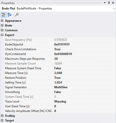
Expert
- Base Frequency: displays the frequency [in Hz] of the basic oscillation required to overcome static friction (only in velocity modes).
- Bode Object Id: If the Bode Plot is to be executed via a "TcCom Object" already set up in the System Manager (e.g. in order to visualize additional process data from the drive), this can take place here via the Object ID.
- Check Drive Limitations: If you want to check via the axes, you can specify this here.
- DynContainerId: sets the ID of the container for dynamic process data. The DynContainer is appended to the EtherCAT device in the TwinCAT project.
- Maximum Steps per Response: sets the number of measuring points per system response for broadband excitations (e.g. MultiSine, Chirp, PRBS).
- Measure Sample Count: indicates the number of setpoint values and actual values from which an interpolation point of the Bode characteristic curve (a frequency point) is calculated.
- Measure System Dead Time: If enabled, the setpoints are linked to the actual values in the controlled EtherCAT segment, e.g., AX8000. This option is only available for the Torque and Velocity modes (primary feedback).
- Measure Time: displays the duration [in s] during which the system is excited to produce a response.
- Setting Time: displays the duration [in s] during which the system settles to the current excitation.
- Signal Generator: displays the excitation type of the signal generator used. The following are available:
- Sine: standard sine oscillation with regard to the set amplitude.
- MultiSine: amplitude-modulated broadband sine.
- Chirp: time-varying, sinusoidal excitation, chirp.
- PRBS: the Pseudorandom Binary Sequence (PRBS) approximates a broadband white noise.
- Smoothing: enables or disables smoothing of the recorded frequency response. The calculation is based on a moving average of the measurement points.
- Smoothing Diameter: sets the radius of the measurement points when smoothing is enabled.
- System Dead Time: the complete dead time can be entered here in seconds.
- Trace Level: sets the detail level of the messages generated by the “Drive Diag –TcCom Object” and output in the Error List. The available options are Always, Error, Verbose and Warning.
- User Dead Time: the dead time in seconds can be specified here.
- Velocity Amplitude Offset: Defines the offset of the signal amplitude in the unit that belongs to the selected axis. If the value is not zero, the axis moves continuously in the desired direction. This is only recommended for freely moving axes.
Target
- Cycle Time: Indicates the last-used cycle time [in ms].
- Oversampling: indicates the oversampling factor to be used. If set to Suggested, the highest useful factor is automatically selected when the recording is started.