I/O master set up in TwinCAT
In TwinCAT, the sensors and axes are linked and the motion simulation is controlled.
Loading parameters and sensors in TwinCAT
- The runtime in the TwinCAT add-in of Autodesk® Inventor® has been initialized.
- The TwinCAT project is open.
- The target in the TwinCAT project was set as "Inventor machine".
- 1. Under System, select the TcCOM object.
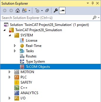
- 2. Click scan
 .
.
- All set axes and sensors from Autodesk® Inventor® are loaded into TwinCAT and displayed as either inputs or outputs. Information from Autodesk® Inventor® is transferred to the PLC project via the inputs. Information from the PLC project is transferred to Autodesk® Inventor® via the outputs.
- If you load new axes of your CAD model into TwinCAT, all existing links are preserved. Only the new axes and sensors are then added.
Linking axes
- The runtime in the TwinCAT add-in of Autodesk® Inventor® is initialized.
- Axes and sensors are loaded in TwinCAT.
- 1. First, create a new Motion configuration by right-clicking MOTION.
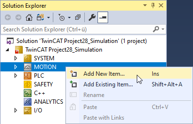
- 2. Select Add New Item.
- The window Insert Motion Configuration opens.
- 3. Enter a name for the configuration.
- 4. Confirm with OK.
- 5. Create an axis by right-clicking Axes.
- 6. Select Add New Item.
- The window Insert an NC axis opens.
- 7. Enter a name for the axis and confirm with OK.
- 8. Right-click on the axis of the TcCom object.
- 9. Select Change Link....
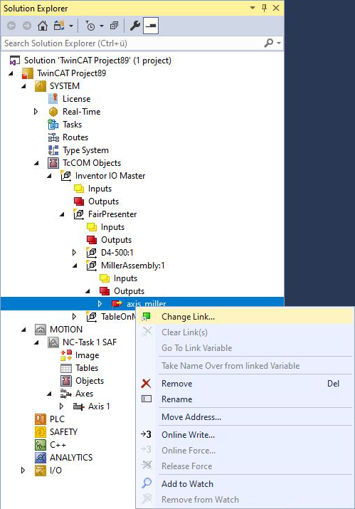
- The Attach Variable window opens.
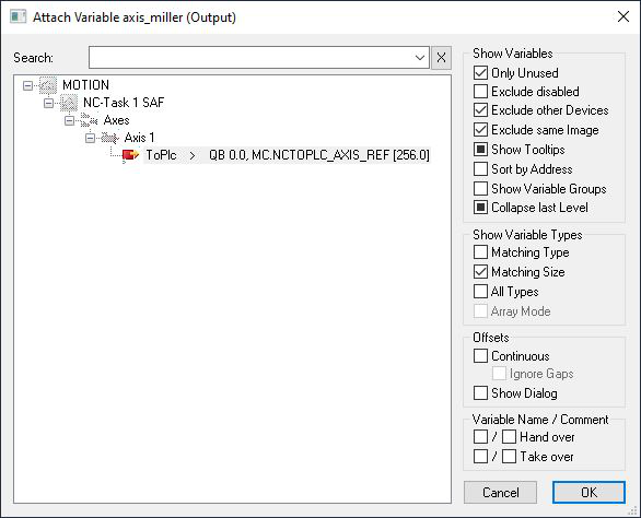
- 10. Select the axis in the MOTION area to which you want to link the axis from CAD.
- 11. If the desired axis is already linked with a project, uncheck the checkbox Only Unused to see all created axes.
- 12. Confirm with OK.
- 13. To set the context, double-click the top node of the TcCom object.
- 14. Select the Context tab.
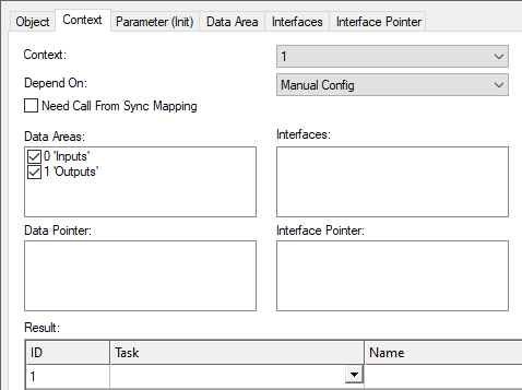
- 15. Assign a task to the object using the drop-down menu Task.
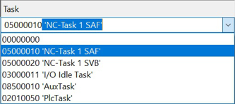
If you use NC axes, it is recommended to select "NC-Task 1 SAF". - 16. Activate the configuration.
- You can now run the simulation.
Conversion of axis positions between TwinCAT project and CAD project
You have the possibility to make settings regarding the axes and sensors in the TwinCAT I/O master. At Unit you have the option of setting the desired unit for an axis, for example. The numerical value written into the I/O master is converted according to the set unit and transferred to Autodesk® Inventor®. In addition, the set offset as well as the limits of the range monitoring from Autodesk® Inventor® are also interpreted according to the set unit.
- 1. Open the desired top node of an object.
- 2. Click the Parameter tab.
- 3. Go to Value and set the units for Offset according to your requirements.
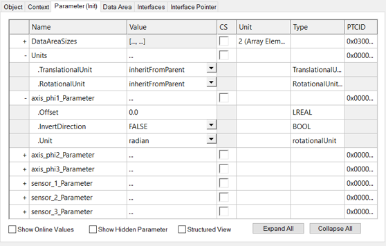
- This results in a conversion depending on the selected unit.
Units
In Inventor, the units can be set according to the model hierarchy after scanning the configuration in the TwinCAT project. One unit for translatory axes and one unit for rotatory axes can be set separately for each assembly. In addition, a unit can be set for each axis according to its type (translatory/rotatory).
By default, the units "millimeter" and "degree" are set in the main assembly. "inheritFromParent" is set by default for all subassemblies and all axes and displacement sensors. This means that all axes and displacement sensors take over the units of the higher-level assembly in this case. If the units are changed based on this default setting at the level of a subassembly, then the units of this subassembly apply to all subordinate subassemblies, axes and displacement sensors. With the selection "inheritFromMainAssembly", subordinate assemblies, axes or displacement sensors can take over the units of the main assembly. Furthermore, it is possible to set a unit individually for each axis or displacement sensor.
The units of Inventor® are irrelevant here. Different units can be set in the CAD model.
Offset and "InvertDirection"
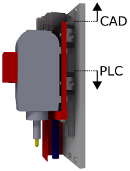
The joint origin in Autodesk® Inventor® and the axis origin assumed by the PLC may not be identical. We recommend setting both the offset and the direction in the TwinCAT project after loading or scanning the axes and sensors.
- 1. First adjust the direction.
- If PLC and CAD coordinate system point in the same direction, then "InvertDirection" is set to "FALSE", otherwise "InvertDirection" is set to "TRUE".
- 2. Set the offset between the two coordinate systems in the respective axis or displacement sensor unit.
- The joint origin is now converted.
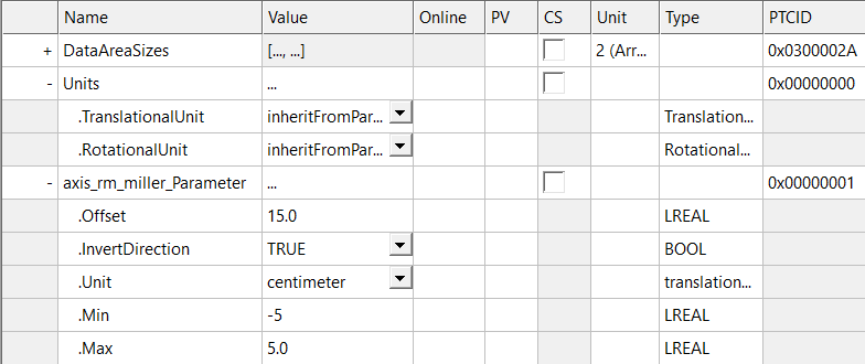
Example
In this example, the vertical motion axis of a miller is parameterized.
The CAD coordinate system points in the opposite direction and has an offset with respect to the PLC coordinate system. The offset is 150 mm. According to the scheme explained above, the unit "cm" was set for the axis. So for this example you have to set "InvertDirection" to "TRUE" and the "Offset" to "15".
The range monitoring of the axis is defined in the PLC coordinate system and in the axis units. In this example, the range monitoring is to trigger when the axis exceeds the defined range of 5 or - 5. Therefore parameterize "-5" for "Min" and "5" for "Max".
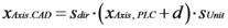
The conversion between axis position in PLC coordinates xAxis,PLC and CAD coordinates xAxis,CAD is described below:
- Factor for direction inversion:

If "InvertDirection" is "TRUE", then sdir = -1 otherwise sdir = 1. - Offset in the specified unit:

- The conversion factor sunit of the selected unit (translatory: micrometer, millimeter, centimeter, meter, inch, foot or rotatory: degree, radian)
- Lower limit of range monitoring in the specified unit xmin.
- Upper limit of range monitoring in the specified unit xmax.
- Conversion of axes from the PLC for Autodesk® Inventor®:
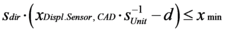
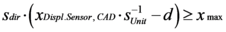
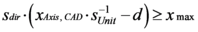
- Condition for range monitoring of axes:
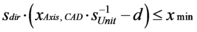
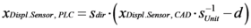
- Conversion of collision sensors, from Autodesk® Inventor® to PLC:
- Conditions for range monitoring for the collision sensors, from Autodesk® Inventor® to the PLC: