Cabling
As already described in the chapter Overview, the EtherCAT simulation was designed to support a virtual commissioning of a plant. The normal cabling for this purpose will look like this:
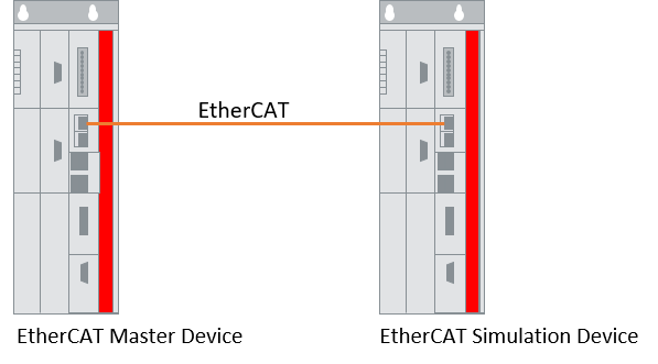
On the left side you can see the control computer, which contains the original control project, which should be used later to control the machine/plant. On the right side you can see a simulation IPC, which contains an EtherCAT simulation device. Both systems are connected by a standard EtherCAT cable.
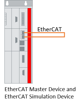
Use of EtherCAT and EtherCAT simulation on the same IPC:
For testing partial functions of the control program (e.g. EtherCAT diagnosis) at an earlier time (before virtual commissioning), the control computer can also be used to simulate the EtherCAT, as long as the control computer has sufficient free network interfaces. Just like every EtherCAT master, every EtherCAT simulation device also requires its own network interface.
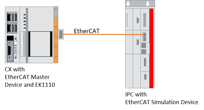
Using a CX as controller
If a CX is used as controller that is to be coupled with a simulation IPC, there may still be EtherCAT devices available depending on the cabling, which must not be taken into account. The following figure shows, for example, the intelligent power supply unit of the CX and an EK1110 EtherCAT extension. Here in the Settings tab a manual device correction can be set, i.e. devices that should not be considered. If this setting is not set, this could result in the EtherCAT master not starting up or the working counter not being calculated correctly.
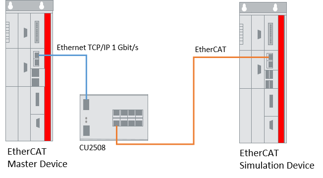
Use of the port multiplier on the original project page:
If a CU2508 port multiplier is used in the real-time configuration of the control computer, the outputs of the port multiplier can be connected to normal network ports on a simulation computer. For these network ports, a corresponding number of EtherCAT simulation devices must be created on the simulation computer.
Notice | |
Use of the port multiplier on the EtherCAT simulation side not supported The use of a CU2508 port multiplier on the EtherCAT simulation side is not supported. If a CU2508 is used on the slave side, it is not contained in the TwinCAT project that exports the configuration file. This CU2508 also only receives the EtherCAT frame after the EtherCAT simulation device. It is thus “invisible” to the EtherCAT simulation. Consequently, neither the Device State nor the Slave Count on the EtherCAT master side display correct values. An EtherCAT diagnosis programmed in the original project would thus display incorrect results. |
Use of the port multiplier on the EtherCAT simulation side:
The use of a CU2508 port multiplier on the EtherCAT simulation side is not supported. If a CU2508 is used on the slave side, it is not contained in the TwinCAT project that exports the configuration file. This CU2508 also only receives the EtherCAT frame after the EtherCAT simulation device. It is thus “invisible” to the EtherCAT simulation. Consequently, neither the Device State nor the Slave Count on the EtherCAT master side display correct values. An EtherCAT diagnosis programmed in the original project would thus display incorrect results.
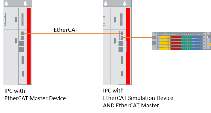
Operation of the EtherCAT simulation in mixed mode
If a machine/plant is to be put into operation step by step or only parts of the machine/plant are to be simulated, cabling can be carried out as shown in the following figure. For this it is necessary that the simulation IPC has 2 free network interfaces. The first network interface is used as an EtherCAT simulation device and is connected with the EtherCAT cable to the control IPC. The second network interface is used as EtherCAT master and connected to the real existing bus devices (see also Mixed operation of real and virtual slaves).