AX2000-B510 Axis (with cyclical CANopen interface)
The Beckhoff AX2000 drive is available with different optional Fieldbus interfaces. Besides these optional Fieldbus interfaces, the drives comes with an integrated CANopen interface already (X6). The AX2000 (from firmware revision 4.94 on, recommended is drive firmware revision 5.53 or higher) is in conjunction with the FC5101 resp. FC5102 capable of resolving the SYNC telegrams according to CANopen specification DS301 V4.01. Therefore, the AX2000 can synchronously update its input and output process image.
Intrduction
Since TwinCAT 2.9, an AX2000-B510 can be mapped in the same way as any other NC supported drive type. Means, an axis e.g. "Axis 1" can be added to the NC task, the CAN specific drive type "AX2000-B510 Drive (CANopen)" can be selected via "Axis type" on the "Settings" tab and this can be linked to a "AX2000-B510" node, configured under I/O Devices -> FC510x (important is here, that a Beckhoff FC5101 or FC5102 is used in this case). Below description explains the AX2000-CANopen-specific settings in detail.
For further information on the AX2000 in CAN operation mode, please consult the manuals to be found under Digital compact Servo amplifier AX2000 on the Beckhoff Download page or Beckhoff Product CD.
"CAN Node" tab
Node Id: The address of the CANopen node (in this case the CAN address of the AX2000 drive) must be assigned here. The drive internal setting of this address can be set via the AX2000 configuration software SR600 or through the ASCII - communication mode. The address given in this dialog must match the internal set drive address.
Profile No.: + Add. Information : This object (0x1000) describes device type (Servo drive) and device functionality (DS402 drive profile).
It is the combination of the following:
Description | Value | Bit | ||
|---|---|---|---|---|
Number of the device profile: | Drive profile | 402 (dec.) | 0x192 (hex.) | 0 - 15 |
Type: | Servo drive | 2 (dec.) | 0x2 (hex.) | 16 - 23 |
Mode bits: | Vendor-specific | 0 |
| 24-31 |
Guard Time (ms): Watchdog-time in milliseconds.
Life Time Factor: Specifies the handling of the "Guard Time". E.g. a here entered "0" deactivates the watchdog. Default value is "3".
Rest of the parameters, see: CANopen device
Adjustments of Address and Baudrate with Drive Configuration Software
The relevant settings for the CAN bus (Node Id, Baudrate,..) can be set via the basic settings of the SR600 software. By default address 1 and baudrate 500kb is set. After changing these values, a "Save to EEProm" with a following coldstart is necessary (SAVE command with following COLDSTART).
Setting the address and baud rate via the serial interface (HyperTerminal)
Setting the address and baud rate via the serial interface (HyperTerminal)
Start the MS Windows Hyperterminal (Start | Run... | hypertrm.exe). Interface setting : '9600 baud, 8 bits, 1 stop bit, no parity, no handshake'. Click in the window and press Enter key.
If the serial cable is connected correctly (X6 ----- RS232), the cursor " -->" appears in the window.
 | Solder bridge If you solder a bridge between pin 7 and 8 on both sockets of the serial cable, the cable is symmetrical and it does not matter which connector is connected to which of the two end devices. |
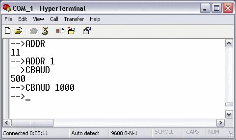
If you want to read the current parameter, enter the ASCII command without parameters (e.g. ADDR). The result is displayed in the next line.
If the address is to be written, the address is appended after the ASCII command (e.g. ADDR1).
AX2000-B510 tab
This tab is used to select the operating mode for the AX2000. Two operating modes are available.
Position Control: The default setting is "Position Control". In this operating mode, the NC cyclically specifies a new position. The travel profile is generated by the TwinCAT NC. In the cycle time of the SEC task (e.g. 10 ms), position values are transmitted to the AX2000 via the CAN interface. There are 3 controllers cascaded into each other on the AX2000 (current (65 µs), speed (250 µs), position (corresponds to the cycle time of the triggering SEC task)). The position control is handled entirely by the AX2000. The AX2000 reports the actual position back to the NC via the cyclic interface.
Velocity control: Optionally, "Velocity Control" can be activated. In this operating mode, the speed serves as the manipulated variable for the AX2000. This reduces the number of internal control loops of the AX2000 to 2, namely the current (65 µs) and speed (250 µs) controller. Compliance with the target position is checked in TwinCAT NC. The actual position is transmitted via the cyclic interface. Since the speed control on the TwinCAT NC requires shorter sampling times, the cycle time of the SEC task is set to 2 ms.
Save: When changing the cycle time of the triggering task (usually this is the NC SEC – task ) or when changing the operating mode (OPMODE), the "SAVE" button should always be pressed.
Coldstart: If the data are stored (approx. 3 s after "SAVE" ) a cold start ("COLDSTART") of the controller is necessary.
| The SAVE and COLDSTART commands can also be executed when the controller is enabled! |
"SDOs" tab
In this tab, the CAN node can be parameterized in the start-up phase via the service data objects (SDOs). Entries with an object index in straight brackets have been generated automatically due to the updated terminal configuration. Additional entries can be managed using "Append", "Insert", Delete" and "Edit".
The SDO's are primarily used for parameterization of the CAN Node and the CAN PDOs. The first two entries define the properties of the TxPDO1:
Object index | Sub Idx | Length | Value | Description |
|---|---|---|---|---|
0x1800 | 1 | 4 | 0x18B | Cob ID (address for the send message of node 11) Default identifier |
0x1800 | 2 | 1 | 1 |
The RxPDO is configured in the same way.
Custom SDOs
Controller configuration
Object index | Sub Idx | Length | Value | Description |
|---|---|---|---|---|
0x6040 | 2 | 2 | 0 | Sets the drive ControlWord to null. The controller is now in the "Switch on disable" state. The AX2000 is ready to be switched on, parameters can be transferred, DC link voltage can be switched on, motion functions cannot yet be executed |
0x3683 | 1 | 1 | 3 | ASCII command: SYNCSRC |
0x363b | 1 | 1 | 3 | Synchronization mode specially adapted to the CAN interface, ASCII command: FPGA |
0x35d5 | 1 | 1 | 40 | Value = Task Cycl / Velocity controller Cycl 40 = 1000 µs / 250 µs, ASCII command: PTBASE |
0x6060 | 0 | 2 | 0xFA | This sets the OPMODE of the drive: 0xFA = Position control 0xFE = Velocity control |
0x3672 | 1 | 1 | 2 | Influencing the CANopen state machine by Enable/Disable. |
The AX2000 has 4 transmit PDOs (TxPDO1..4) and 4 receive PDOs (RxPDO1..4). The content of these messages (PDOs) depends on the operation mode and the mapping. There are 7 predefined RxPDOs and 6 predefined TxPDOs. In addition to this, there is an option to compose the message.
| Do not map every object Not every object can be mapped in a freely definable PDO. |
For the "Position control", both the RxPDO and the TxPDO were configured freely. For "Velocity control", the TxPDO was taken from the pool of predefined PDOs. The RxPDO was defined freely.
Example:
Object index | Sub Idx | Length | Value | Description |
|---|---|---|---|---|
0x2600 | 0 | 1 | 0x25 | Selection of a freely definable RxPDO (37..40) |
0x1600 | 0 | 0 | 0 | Delete mapping |
0x1600 | 1 | 4 | 0x60400010 | The first element of the message is the ControlWord (0x6040) Subelement SI (0x00) Length (0x10) 16-bit |
0x1600 | 2 | 4 | 0x20220420 | The first element of the message is the TargetPosition (0x2022) Subelement SI (0x04) Length (0x20) 32-bit |
"ADS" Tab
Via the shown AmsNetID + Port number (address) it is possible to read and write parameters from/to the AX2000 (e.g. from PLC).
Example: To read the divice type, the object information Index: 0x1000, SI: 0x0 is used.
"DIAG" Tag
Under this tab, detailed error messages are displayed. With a wrong configured Additionional Information for example, the CANopen Master e.g. detects the difference between the configured value and the one contained in the drive. If everything is ok and the drivy is ready for operation, it shows"".
AX2000-B510 Diagnosis Inputs
The diagnosis Inputs of an AX2000-B510 don't differ from the diagnosis inputs of other TwinCAT CANopen nodes (see also: "FC510x: Box-Diagnosis").
Process Image
The TxPDO's and RxPDO's are to be seen from the slave point of view. The input process image (TxPDO) contains a "State" and "ActualPos" process variable. The output process image (RxPDO) contains a "Ctrl" and a "NominalPos" variable.
"State": Object information Index: 0x6041, SI: 0x0, Len: 2
Bit | Name | Bit | Name |
|---|---|---|---|
0 | Ready to switch on | 8 | Manufacturer specific (reserved) |
1 | Switched on | 9 | Remote (not supported) |
2 | Operation enable | 10 | Target reached |
3 | Fault (i.V.) | 11 | Internal limit active (not supported) |
4 | Disable voltage | 12 | Operation mode specific (reserved) |
5 | Quick stop | 13 | Operation mode specific (reserved) |
6 | Switch on disabled | 14 | Manufacturer specific (reserved) |
7 | Warning | 15 | Manufacturer specific (reserved) |
"ActualPos": Current drive position. Object information Index: 0x2070, SI: 0x3, Len: 4
Via this index, the incremental encoder value (drive emulated) of the current position can be read. One revolution has an incremental value of a 20 bit resolution.
That means: 1 revolution 2 ²º increments = 1048576 increments. The adjusted resolution per revolution can be checked with the ASCII command "PRBASE".
Default value: 20 bit/rev.
"Ctrl": Object information Index: 0x6040, SI: 0x0, Len: 2
Bit | Name | Bit | Name |
|---|---|---|---|
0 | Switch on | 8 | Halt (intermediate stop command) |
1 | Disable Voltage | 9 | (reserved) |
2 | Quick Stop | 10 | (reserved) |
3 | Enable Operation | 11 | Acknowledge lag-distance and watchdog |
4 | Operation mode-specific | 12 | Reset position |
5 | Operation mode-specific | 13 | Manufacturer specific (reserved) |
6 | Operation mode-specific | 14 | Manufacturer specific (reserved) |
7 | Reset Fault (only active after error messages) | 15 | Manufacturer specific (reserved) |
"NominalPos": Setpoint position. Object information Index: 0x2022, SI: 0x4, Len: 4
Via this parameter, the incremental value of the setpoint position is prescribed.
"NominalVelo": Setpoint velocity. Object information Index: 0x2060, SI: 0x0, Len: 4
Via this parameter, the scaled setpoint velocity is prescribed.