M3000
The absolute encoder M3000 has an integrated Beckhoff Lightbus interface and provides persistent position displacement with a measurement range of 24 bit.
Variables
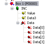
Variable | Data type | Description |
|---|---|---|
Value | UINT24 | This 24-bit wide input variable contains the current position value of the absolute encoder. |
Data3 | USINT | This input variable is a "spare byte". This byte is necessary since the above-described Value variable is intentionally 24-bit but Lightbus modules by default have a 32-bit interface for In- and Out-direction. Therefore, Data3 gets also mapped by default while linking the encoder to a NC axis interface. |
Data | ARRAY [0..3] OF USINT | The data bytes of this array are output variables* to the encoder. * Only used in Programming Mode of the encoder (not used within TwinCAT NC)! |
TwinCAT NC Encoder
If you add an axis to the NC part of the System Manager, you must select the adequate NC-Encoder type. For the M3000, the following types are available (selection manipulates the parameter 'Encoder Mask (Maximal Value)' on the tab 'Global' which is shown further below):
Requirements
NC-Encoder Type | TwinCAT NC Tab | Description |
|---|---|---|
Encoder connected to M3000 (24bit Multi-Turn) | Axis x_Enc | 'NC-Encoder' | If this encoder type gets selected in TwinCAT NC and linked to the M3000 module, the NC will interpret the bit pattern received from 'Value' as 24bit multi-turn value. |
Encoder connected to M3000 (25bit Multi-Turn) | Axis x_Enc | 'NC-Encoder' | If this encoder type gets selected in TwinCAT NC and linked to the M3000 module, the NC will interpret the bit pattern received from 'Value' as 25bit multi-turn value. |
Encoder connected to M3000 (12bit Single-Turn) | Axis x_Enc | 'NC-Encoder' | If this encoder type gets selected in TwinCAT NC and linked to the M3000 module, the NC will interpret the bit pattern received from 'Value' as 12bit single-turn value. |
Encoder connected to M3000 (13bit Single-Turn) | Axis x_Enc | 'NC-Encoder' | If this encoder type gets selected in TwinCAT NC and linked to the M3000 module, the NC will interpret the bit pattern received from 'Value' as 13bit single-turn value. |
After a possible replacement of the encoder, it is important to adapt the position bias and eventually the counting direction of the new encoder. This is possible via the tab 'Global' at the 'Axis x_Enc' axis interface with the parameters
- 'Position Bias' resp.
- 'Invert Encoder Counting Direction'.
In operation, the count value should always range between the minimal (0) and the maximal counter value of the encoder type, taking the complete moving distance into account.
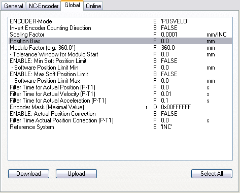
TwinCAT NC - Encoder 'Global'
The available dialog for the possible manipulation of 'Position Bias' and 'Invert Encoder Counting Direction' is shown below:
The following operation mode is only described because of completeness since it is normally not in use while operating with TwinCAT.
The M3000 absolute encoder is programmable via the Lightbus, which can therefore even happen with the aid of the PLC application. The programmed settings get stored within the encoder. If the programming mode gets (unlikely) used within TwinCAT, the programmer must take care that the TwinCAT NC runtime is stopped during this operation!
Programming mode:
During programming mode, the output as well as the input bytes are in use. The 4 input and output bytes of the 32-bit module have the following function:
Data[0] = value to be written to the encoder (Output)
Data[1] = status bits (acknowledge) of the transmission block from the encoder (Input, Value) with the following meaning:
Bit 0: = feedback of mode change towards programming mode
Bit 1: not used
Bit 2: = acknowledge data block transmission Ok., data stored
Bit 3: = acknowledge data byte accepted
Bit 4 -7: not used
Data[2] = feedback of written value from encoder (Input, Value). Means, the encoder sends from Data[0] received values back (hopefully ;-).
Data[3] = Control bits in programming mode (Output). These bits control the programming functions of the encoder (flow-control/handshaking). During programming mode operation this byte gets mirrored in the Data3 input variable.
The bits have the following meaning:
Bit 0: '0' = count mode, '1' = programming mode
Bit 1: = 'Preset 1' take-over request to encoder
Bit 2: = 'Preset 2' take-over request to encoder
Bit 3: = strobe bit for transmission of data byte
Bit 4-6: not used
Special function Bit 7: Enable Latch function