Sync Unit Assignment
A Sync Unit describes a module, that defines a set of process data, that should be exchanged synchronously and consistently between the master and one or more EtherCAT slave devices. For each Sync Unit a separate EtherCAT command is sent synchronous with the cycle, to exchange the process data with the EtherCAT slave devices. Every Sync Unit has a diagnostic input, that is synchronous with the cycle and shows, if the complete data is valid (see WcState). Sync Units are useful in applications, where parts of the machine should keep on operating, although other parts have dropped out or have been deactivated.
For each EtherCAT slave device, one can define one or more process data areas, that should be exchanged synchronously and consistently. These individual process data areas can be configured in the Process Data tab of a slave device. Normally every PDO object is assigned to the same process data area (Sync Unit). This is indicated by the column SU (Sync Unit) in the PDO List View:
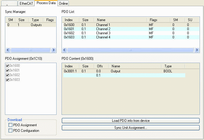
In the example above all channels are assigned to the Sync unit 0. The number of independent process data areas of an EtherCAT slave device, depends on the implementation and resources of its EtherCAT slave controller (Sync Manager and Fmmu). The Sync Units of the EtherCAT slave devices can be assigned to Sync Units of a specific Sync Task. These Sync Units are marked with freely definable names. One can either assign each Sync Unit of a slave individually to a Sync Unit, by pressing the "Sync Unit Assignment..." on the "Process data" tab of a slave (see dialog above), or one can assign one or more slave Sync Units by pressing the "Sync Unit Assignment..." button on the "EtherCAT" tab of the EtherCAT master device:
Sync Unit Assignment dialog
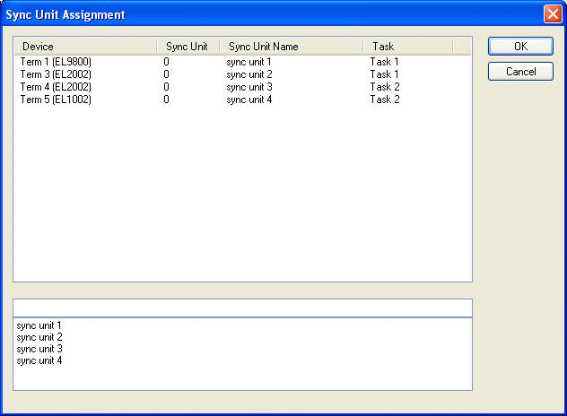
To assign a Sync Unit to a process data area of an EtherCAT slave device, select an entry in the list view above. Then type the name of the Sync Unit in the edit field below or select one of the entries in the list box below. In the example above 'sync unit 1' of Task 1 is assigned to Sync Unit 0 of Term 1 and 'sync unit 2' of Task 1 is assigned to Sync Unit 0 of Term 3.
The 'EtherCAT' tab of the EtherCAT slave devices displays the cyclic frames sent by the EtherCAT master for the process data communication:
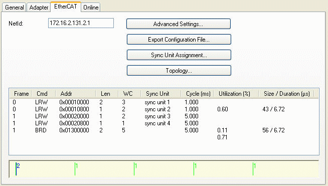
For each sync task taking part in process data communication a separate frame is sent. The maximal number of sync tasks is set to 4 by default. To change the maximal number of sync tasks, one has to open the Advanced Settings Dialog and select the Sync Tasks page. It is possible to assign one or more Sync Units for a specific task. Each of these Sync Units is assigned to a process data area of a slave device. For each Sync Unit of a sync task the EtherCAT frame contains a separate EtherCAT command. In the example above the first EtherCAT command of the first EtherCAT frame exchanges the process data of the EtherCAT devices assigned to the Sync Unit 1 of Task 1. In this case it is only the one EtherCAT slave device Term1(EL9800)(see Sync Unit Assignment dialog above). For each Sync Unit of a task an expected working counter is calculated, that is displayed in the column 'WC'.
Working Counter: The working counter of an EtherCAT command is a 16-bit counter. The counter is incremented by each EtherCAT slave, that is successfully addressed by the command. If only inputs are read from the EtherCAT slave device, the working counter is incremented by 1. If outputs are written to the EtherCAT slave device, the working counter is incremented by 2. If both inputs and outputs variables are exchanged the working counter is incremented by 3. If the working counter is incorrect the EhterCAT master discards the received inputs of the EtherCAT command.
For each frame the master has a diagnostic input 'FrmXWcState' (X =frame number), that shows the working counter states of the individual EtherCAT commands of the frame (see FrmXWcState). With 'FrmXWcState' it is not possible to verify which Term is responsible for the incorrect working counter. To retrieve more detailed information about the states of the individual slave devices, one has to read out the input variable InfoData.State of the slaves.
Example:
- Open a new System Manager Project
- Add a EtherCAT device to the I/O devices in the tree view of the system manager
- Append an EK1100 and three EL1004 to the EtherCAT device.
- Expand the entry 'System-Configuration' in the tree view of the system manager
- Open the context menu of 'Additional Task' by right clicking on the subitem 'Additional Task' of 'System-Configuration'
- Select the menu entry 'Append Task...' to add Task1
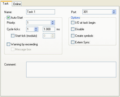
- In the tab 'Task' of the additional task 'Task1' check the Auto-Start box and change the cycle time to 1 ms.
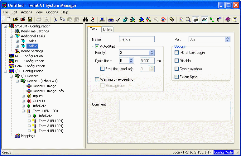
- Repeat step 5 to 7 to add another task and set the cycle time to 5ms. The current configuration should look like this:
- Next we will add input variables to the Task 2 and map these to the inputs of the terms. Right click on the entry 'Inputs' of Task 2 and select 'Insert Variable...' in the context menu. In the 'Insert Variable' dialog select 'Bit' as variable type and press the 'OK' button.
- Double click on the newly created variable and map this variable to first input of Term 2. Add another two variables to Task 2 and map these to the first input of Term 3 and the first input of Term 4 :
- Select the EtherCAT device in the tree view of the system manager and open the 'EtherCAT' tab on the right:
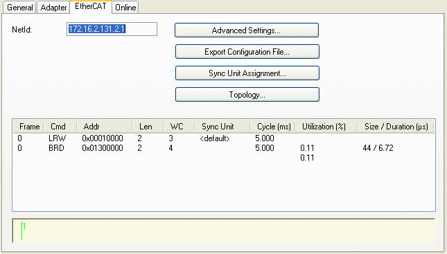
In the list view of this page we can see that one frame containing two EtherCAT commands is sent by the master. The first command is a LRW(Logical Read Write) command and is responsible for reading the inputs and writing to the outputs of one or more slave devices. The column 'Sync Unit' specifies the Sync Unit this command is assigned to. Because we have not yet assigned any Sync Units, the default Sync Unit is used. Because all variables are mapped to Task2, the value 'Cycle (ms)' is set to 5ms, the cycle time of Task2. The expected working counter (WC) is set to 3, one for each slave device. This is the case because the connected slaves devices have only input variables. - Next we will add two Sync Units and will assign one to the process data of the first EL1004(Term 2) and the others to Term 3 and Term4 . Press the button 'Sync Unit Assignment...' on the EtherCAT page to open the 'Sync Unit Assignment' dialog :
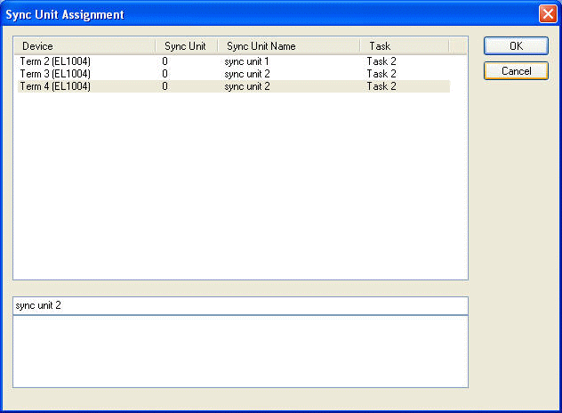
Select the first entry and type 'sync unit 1' into the edit field below. Now we have created a new Sync Unit called 'sync unit 1' and have assigned it to the Sync Unit 0 of Term2(EL2004). Then select the Term 3 and type 'sync unit 2' into the edit field and finally select term 4 and type 'sync unit 2' into the edit field again. Press the 'OK' button to close the dialog: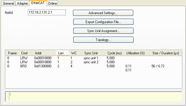
Because of the Sync Unit assignment another EtherCAT command has been added to the list of cyclic commands. The first 'LRW' command is responsible for the process data communication of all EtherCAT slave devices belonging to the Sync Unit 'sync unit 1'. In our case this is only the Term 2. The second 'LRW' command is responsible for the process data communication of all EtherCAT slave devices belonging to the Sync Unit 'sync unit 2' (here Term 3 and Term 4). Now it is possible to monitor the working counter state of the first command and second command separately with help of the 'Frm0WcState' input variable: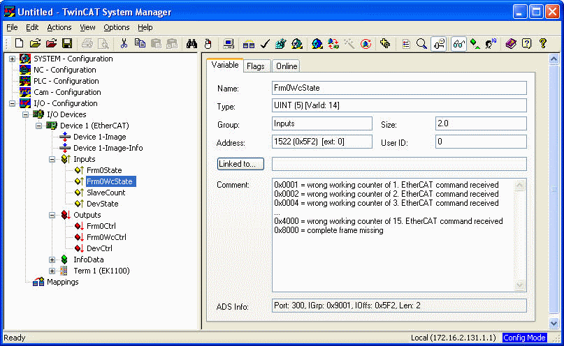
If Term 2 returns an incorrect working counter bit 1 of the variable 'Frm0WcState' would be set to 1, indicating that a wrong working counter has been received for the first EtherCAT command. Therefore, the received data will be discarded and will not be copied to the input variable. If the second EtherCAT command has a correct working counter the received data for Term 3 and Term 4 will be processed normally. If the second EtherCAT command returns an incorrect working counter, bit 2 of 'Frm0WcState' is set. This indicates that either Term 2 or Term 3 or even both Term 2 and Term 3 have not incremented the working counter correctly. Therefore, it is not possible to verify with 'Frm0WcState', which Term is responsible for the incorrect working counter. To retrieve more detailed information about the states of the individual slave devices one must read out the variable InfoData.State. - Finally we will add a input variable to Task 1and map this variable to Channel 2 of Term 4:
- Select the EtherCAT device in the tree view of the system manager and open the 'EtherCAT' tab on the right:
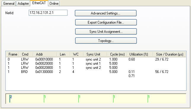
Here we can see that another frame has been added to the list. The first frame consists of only one LRW EtherCAT command with the cycle time of 1 ms, corresponding to the cycle time of Task 1 . This command is sent cyclically by the Task 1 and is responsible for reading the inputs of Term 4. Although the first input of Term 4 is mapped to the Task 2 the input is also read out by the EtherCAT command belonging to the Task 1. This is the case because Term 4 only has one process data area. In this case the task with the highest priority is selected for the process data communication with the slave device. The second frame is sent cyclically by the Task 2 with a cycle time of 5ms. The BRD command is always sent by the task with the lowest priority. The individual Sync Units can be viewed by pressing the 'Sync Unit Assignment ...' button: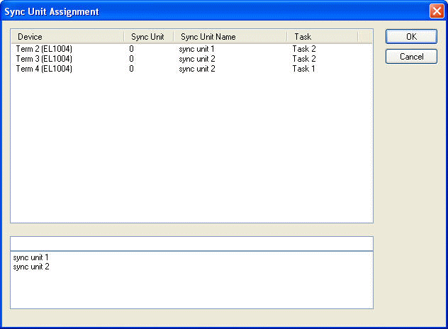
Here we can see that the Sync Unit 0 of Term 4 is assigned to 'sync unit 2' of Task 2. Because we now have two frames, the input variables 'Frm1State' and 'Frm1WcState' have been added to the device. With the help of these inputs the state and the working counter state of the second frame can be read out.