EtherCAT - Setting up the Bus Terminals
Hardware Requirements:
- embedded PC CX1020
- CPU base module C1020-0123: 512 MB Flash memory, WindowsXP embedded
- System interface CX1020-N010: one DVI-I and two USB interfaces.
- Power supply unit CX1100-0004 with EtherCAT interface - or a conventional IPC with Windows 2000, XP or Vista and at least one unused Ethernet port.
- EtherCAT I/O-Terminals:
- EL2004: 4x Digital-OUT, 24V DC, 0.5A, typical cycle time 90 µs
- Further I/O terminals are possible
This instruction is written for an embedded PC CX1020. But it is applicable to every other Windows PC, too.
Setting up the terminals:
Set up the CX1020 as shown in the drawing below. (The drawing shows an example configuration.)
Power the CX1020 with 24 V DC.
Hardware Documentation
Further infomration about the hardware connection can be found in the correspondent hardware documentation.
Starting the TwinCAT real time server
Now, start the TwinCAT real time server in the 'Config Mode', unless you have already done so, so that the TwinCAT message router is active.
Starting the TwinCAT System Manager
Once the system has been started, the color of the icon changes from red to blue. Now start the TwinCAT System Manager by selecting 'Start'-> 'Programs' -> 'TwinCAT System' -> 'TwinCAT System Manager'.
The items of the TwinCAT System Manager:
In the first line is the name of the project, (here 'unbenannt'), amount there´s the command line (menu) and the toolbar. In the last line you can see the status of the system, in this picture, the system is running (RTime). The two windows in the middle contains the configuration of the system. In the following steps you´ll configure the system.
The system configuration is shown as a tree structure on the left side of the System Manager. It consists of the following three main points:
Configuration | Meaning |
|---|---|
System configuration | Set the system and the Real Time Parameters |
PLC configuration | All PLC Projects that are required to be configured |
I/O configuration | In order to link the controller to the process level, the system needs interfaces. This entry offers a list of all interfaces. |
Further System components are possible listed (e.g. Cam server or NC configuration).
PLC Configuration:
The individual PLC projects must be made known to the System Manager so that TwinCAT can access the variables of the PLC programs. To do this, press the right mouse button while the mouse pointer is over 'PLC configuration'
A context menu opens, in which you must select the 'Append IEC project…' entry.
Switch to the '\TwinCAT\Samples\FirstSteps\' directory and select the 'maschine.tpy' file.
A further point has been added under 'PLC configuration' which bears the name of the PLC project.
The + and the - symbols indicate whether the entry contains a further subpoints. By clicking these symbols, you open or close the entries below them. The following structure appears if you open the tree as far as possible:
In the picture above you can see that your example program contains a task named 'standard'.
I/O Configuration
Add a device
Insert the I/O devices in the same way like the PLC configuration.
With TwinCAT 2.9 the devices can be scanned automatically ('Scan devices'). Found devices are listed afterwards under I/O devices in the tree view.
The the target system has to be in Config Mode for this function.
Select the 'I/O devices' entry with the right mouse button. A context menu opens, in which you must select the 'Scan devices' entry.
The following dialog opens:
TwinCAT scans the connected peripheral and lists the found devices -> 'OK'.
The System-Manager wants to search for boxes (Bus Couplers, Bus Terminals, Busterminal Controllers or Fieldbus Box Modules) at all channels of the CX1020 -> 'Yes'.
To activate the Free Run Modus confirm with ->'Yes'.
(Found I/O devices can be set to Free-Run mode, that means, e.g. I/O channels of Bus Terminals can be set (written) to a certain status without having any PLC project or other triggering task active.)
Now, the System Manager shows the found I/O configuration:
It goes without saying that you can rename the standard designations (device 1, box 1, terminal 1 etc.) To do this, slowly double click the corresponding name and enter the new designation.
Assigning variables to the input/output channels:
Up to this point, the complete hardware needed for the above example program has been configured. Next, the individual variables from the PLC project must be assigned to the individual input/output channels.
To do this, mark the terminal you wish to configure. A dialog box containing the input and output channels of the connected peripheral opens. Select the 'Variables' tab.
You see a list of the four output channels, but they are still all free. Select for all variables the wanted digital output channel.
Terminal EL1014 | PLC variables | Meaning |
|---|---|---|
Channel 1 (= output 1) | engine | Stepper motor control |
Channel 2 (= output 2) | deviceUp | Drill up control |
Channel 3 (= output 3) | deviceDown | Drill down control |
Assignments of the bus terminals (sample configuration)
Saving the project:

You should save the configuration at this point to make sure you can access it later on. To do this, run the 'Save as…' command from the 'File' menu.
Mapping variables:

You have now configured the complete system for the above example program. You must now create the allocation for the registry. To do this, go to the 'Create mapping' command in the 'Actions' menu. Under the 'Mappings' tree entry, you now see 'Maschine (Standard) - Device 2 (EtherCAT)'. Click this entry. The following window opens on the right side:
You can define whether the data flow from A to B or from B to A is to be displayed. In this case, Image A corresponds to the process image of the PLC variables, i.e. the input/output variables. Image B corresponds to the process image of the I/O devices, in this case of the EtherCAT bus coupler. Each variable or bus terminal is color highlighted in the process image. If you stop on one of these areas with the mouse, a small display box appears in which the precise designation is shown. With a right mouse click you can zoom the picture.
Writing the configuration to the registry:

As the last step, you must save the configuration to registry because the information stored there is evaluated when you start TwinCAT. Run the 'Save in registry…' command from the 'Actions' menu. If an older configuration is already stored there, a safety prompt will appear, which you must confirm.
Restarting TwinCAT:
TwinCAT wants to restart in the 'Run Mode' to take the changes.
By the new configuration the loaded program on the Control doesn´t exisit anymore. Bus Terminals indicate their signal state by means of light emitting diodes.
Open the program 'PLC Control' and select the command 'Login' in the menue 'online'. The message appears 'No program on the control!' Confirm with 'OK', and the program is loaded to the PLC.
With 'Online' -> 'Start' the programm starts with the new configuration.
The individual PLC variables are now output on the bus terminal EL2004. The Bus Terminals indicate their signal state by means of light emitting diodes.
Boot settings
The project has to be reloaded as soon as the PLC is restarted. Alternatively, you may create a boot project. This remains stored in the registry and starts as soon as the TwinCAT RealTime Server is started, provided that the configuration has not changed.
First, specify which runtime system is to include a boot project in the System Manager menu 'PLC Configuration' under the 'PLC Settings' tab, where the number of available runtime systems can also be specified.
Load the associated programs via 'Add PLC project' in the System Manager, then link the I/Os and activate the configuration. Now execute the command 'Online' -> Creating a boot project' with TwinCAT PLC Control for each associated PLC program after login ('Online' -> 'Login'). The associated command can be used to delete it again. Please ensure that the associated runtime systems match. Log out again and close PLC Control.
Save your System Manager project.
 | Boot project is retained If the boot project is not overwritten or deleted, it remains loaded in the PLC until you create a new boot project for this runtime system or delete it. |
If TwinCAT is to automatically process one or several PLC programs on system startup, the number of runtime systems must be specified and the boot projects loaded (see above).
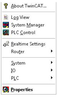
Now open the 'Properties' menu via the TwinCAT button in the taskbar:
In the 'System' tab, you must select the 'Enable' option under 'Auto-Boot'. If you want the PLC program to start completely without your intervention, you must also enter your login data for 'Auto Logon'. If this option is not checked, a user login is required first after the system start:
The settings for 'Auto-Boot' are identical with the setting 'System configuration' -> 'Boot settings' in the System Manager.
Likewise, the settings of the 'PLC' tab are identical to the settings under 'PLC Configuration' -> 'PLC Settings' in the System Manager:
After a restart of the system TwinCAT will start in 'Run' mode (assuming auto logon) and start to process the loaded and released boot projects independently.