Lightbus - Setting up the Bus Terminals
Hardware Requirements:
- PC Interface card: FC2001
- Bus coupler: BK2000
- 3 digital outputs, 24V: 2x KL2032
- Bus end terminal: KL9010
This example is exactly appropriate for the contents of the Beckhoff Lightbus demokit (TC9910-B200-0100). The hardware is however exchangeable. In this case, the configuration of the I/O devices has to be changed
Setting up the terminals
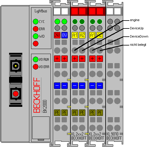
Set up the bus coupler and the bus terminals as shown in the drawing below:
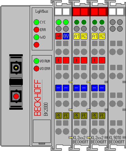
Connect the bus coupler to the PC interface card and power the bus coupler with 24 V DC.
Hardware Documentation
Further information about the hardware connection contains the hardware documentation of the demokit.
Starting the TwinCAT real time server:
Now, start the TwinCAT real time server, unless you have already done so, so that the TwinCAT message router is active.
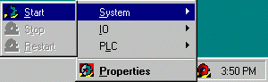
Starting the TwinCAT System Manager
Once the system has been started, the color of the icon changes from red to green. Now start the TwinCAT System Manager by selecting 'Start'-> 'Programs' -> 'TwinCAT System' -> 'TwinCAT System Manager'.
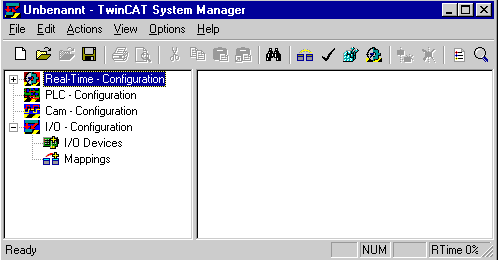
The items of the TwinCAT System Manager:
In the first line is the name of the project, (here 'unbenannt'), amount there´s the command line (menu) and the toolbar. In the last line you can see the status of the system, in this picture, the system is running (RTime). The two windows in the middle contains the configuration of the system. In the following steps you´ll configure the system.
The system configuration is shown as a tree structure on the left side of the System Manager. It consists of the following four main points:
Configuration | Meaning |
|---|---|
Realtime | Set the Real Time Parameters |
PLC | All PLC Projects that are required to be configured |
Cam | Add the cam server |
I/O | In order to link the controller to the process level, the system needs interfaces. This entry offers a list of all interfaces. |
PLC Configuration:
The individual PLC projects must be made known to the System Manager so that TwinCAT can access the variables of the PLC programs. To do this, press the right mouse button while the mouse pointer is over 'PLC configuration'
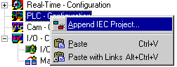
A context menu opens, in which you must select the 'Append IEC project…' entry.
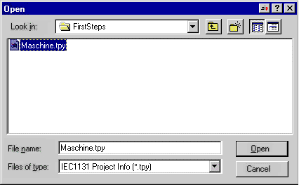
Switch to the '\TwinCAT\Samples\FirstSteps\' directory and select the 'maschine.tpy' file.
A further point has been added under 'PLC configuration' which bears the name of the PLC project.
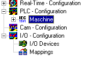
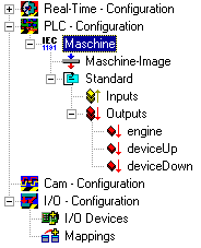
The + and the - symbols indicate whether the entry contains a further subpoints. By clicking these symbols, you open or close the entries below them. The following structure appears if you open the tree as far as possible:
I/O Configuration:
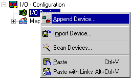
Once the PLC project has been added to the PLC configuration, and thus all variables that are in the process image are known, it is necessary to specify the I/O configuration. Select the 'I/O devices' entry with the right mouse button. A context menu opens, in which you must select the 'Add device' entry.
Selecting an I/O device:
The following window opens. Select the device type, in this case 'I/O lightbus FC200x, PCI '. You can choose the device name freely.
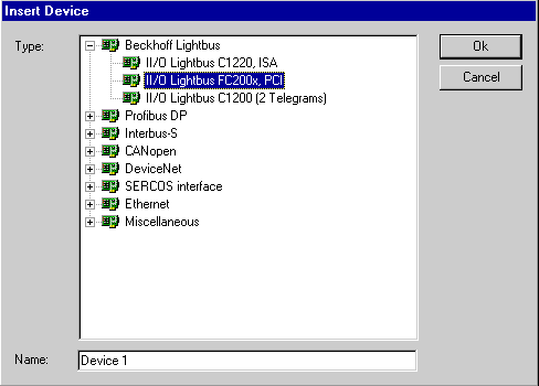
On the right hand side, a dialog box now opens in which you can specify the configuration of the interface card. One important setting under the 'FC2001' slider, for example, is the I/O address of the lightbus card. You can use the specified entries if you have not made any changes to the default settings of the card.
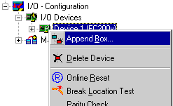
Adding a bus coupler:
Open the context menu of the FC2001 card (device 1) and select the ‘Add box…’ command.
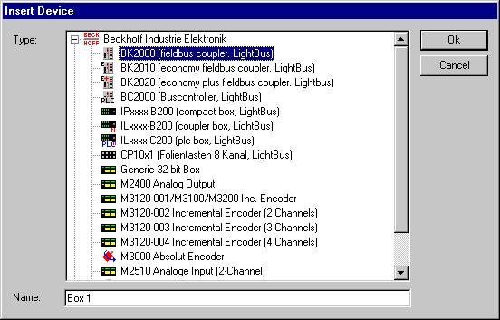
Selecting a bus coupler:
Select the field bus module type, in this case 'BK2000'. You can choose the field bus module name freely.
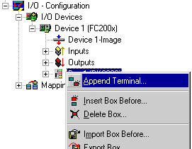
Adding a bus terminal:
Open the context menu (press the right mouse button) of the BK2000 (box 1) and select the 'Add terminal…' command.
Selecting a bus terminal:
Select the 2032 terminal. To do this, move the mouse pointer to the - sign and click to close the selection of digital input terminals. Click on the '+' sign for the digital output terminals to open the new selection and click on the desired KL2032 terminal to select it. Confirm your selection with 'OK'.
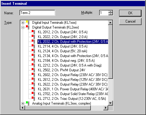
You can choose the bus terminal name freely.
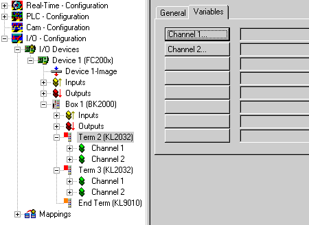
The sample program requires 3 digital outputs. To insert the second bus terminal, repeat the steps.
The Bus end Terminal KL9010 is inserted automatically by the System Manager.
End of configuration:
The configuration then has the following breakdown:
It goes without saying that you can rename the standard designations (device 1, box 1, terminal 1 etc.) To do this, slowly double click the corresponding name and enter the new designation.
Assigning variables to the input/output channels:
Up to this point, the complete hardware needed for the above example program has been configured. Next, the individual variables from the PLC project must be assigned to the individual input/output channels.
To do this, mark the terminal you wish to configure. In the case of terminal 1 (four digital outputs), a dialog box containing the 'General' and 'Variables' sliders opens on the right. Select the 'Variables' tab.
Obove you see a list of the two output channels, but they are still all free. To configure channel 1, select the corresponding button ('channel 1…'). The following dialog box opens:
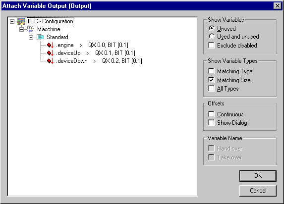
All output variables are now listed in this dialog box. Select the first variable (engine) and confirm your entry by clicking 'OK'. Proceed analogously with the second output variable.
The first bus terminal is attached:
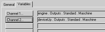
The second bus terminal is also assigned, channel 1 is assigned to device.down. Channel 2 of this terminal remains unassigned.
Assigning variables
Terminal 2 | PLC variables | Meaning |
|---|---|---|
Channel1(=output 1) | engine | Stepper motor control |
Channel2 (=output 2) | device.Up | Drill up control |
Terminal 3 | PLC variables | Meaning |
|---|---|---|
Channel1 (=output 3) | device.Down | Drill down control |
Channel2 (=output 4) | - | free channel |
Assignments of the bus terminals:
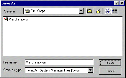
Saving the project:

You should save the configuration at this point to make sure you can access it later on. To do this, run the 'Save as…' command from the 'File' menu.
Mapping Variables:

You have now configured the complete system for the above example pro-gram. You must now create the allocation. To do this, go to the 'Create allocation' command in the 'Actions' menu. Under the 'Allocations' tree entry, you now see 'Standard device 1(FC2001)'. Click this entry. The following window opens:
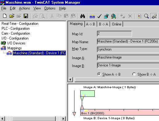
In the dialog box, you can define whether the data flow from A to B or from B to A is to be displayed. In this case, Image A corresponds to the process image of the PLC variables, i.e. the input/output variables. Image B corresponds to the process image of the I/O devices, in this case of the bus coupler BK2000. Each variable or bus terminal is color highlighted in the process image. If you stop on one of these areas with the mouse, a small display box appears in which the precise designation is shown.
Writing the configuration to the registry:

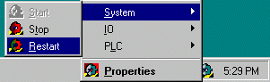
As the last step, you must save the configuration to Windows NT registry because the information stored there is evaluated when you start Twin-CAT. Run the 'Save in registry…' command from the 'Actions' menu. If an older configuration is already stored there, a safety prompt will appear, which you must confirm.
Restarting TwinCAT:
You must restart the system so that TwinCAT will accept the change.
The individual PLC variables are now output on the bus terminal KL 2032. The Bus Terminals indicate their signal state by means of light emitting diodes.