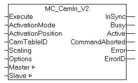
MC_CamIn_V2
MC_CamIn_V2 is a further development of the function block MC_CamIn and is able to operate with several superimposed cam plates (Multi-Cam). When MC_CamIn_V2 is first called it creates a master/slave coupling with the cam plate. Subsequent calls during runtime can be used to superimpose additional cam plates for the same slave axis or remove them again. The switching rules, in particular the time or position, can be specified.
MC_CamIn_V2 can only be used as an alternative to MC_CamIn. The two function blocks cannot be used together for the same slave axis. For addition, replacement and removal of cam plates the function blocks MC_CamAdd, MC_CamExchange and MC_CamRemove are available as alternatives. All operations can also be carried out with MC_CamIn_V2.
The status flag Axis.Status.CamTableQueued (AXIS_REF) can be used to check whether a cam plate is queued for addition or switchover.
The block can be used from a runtime version TwinCAT 2.11 R2
Important:
ActivationMode (time and/or position from which the operation takes place)
CamOperationMode (adding, switching or removal of superimposed cam plates)
Inputs
VAR_INPUT
    Execute : BOOL;
    ActivationMode : MC_CamActivationMode := MC_CAMACTIVATION_INSTANTANEOUS;
    ActivationPosition : LREAL;
    CamTableID : MC_CAM_ID;
    Scaling : ST_CamScalingData;
    Options : ST_CamInOptions_V2;
END_VAR
Execute | The command is executed with a rising edge at input Execute. | |
ActivationMode | The ActivationMode is used to specify the time and/or position at which the cam plate coupling or switchover is to take place. | |
ActivationPosition | Optional master position at which a cam plate is switched, depending on the ActivationMode. | |
CamTableID | ID of the cam plate used for the coupling | |
Scaling | Optional scaling parameters for the cam plate | |
Options
| Data structure with further coupling and switching options: | |
Interpolation type | Interpolation type for position tables. Not required for motion functions. | |
CamOperationMode | The CamOperationMode defines the way the specified cam plate (CamTableID) has to act in the coupled system. Cam plates can be added, switched or removed. | |
ReferenceCamTableID | Optional ID of a cam plate that is already active in the coupling. This ID is specially required for operations that would otherwise be ambiguous, e.g. replacement of certain cam plates in multi-couplings. In unambiguous operations the value can remain 0. | |
Outputs
VAR_OUTPUT
    InSync         : BOOL;
    Busy           : BOOL;
    Active         : BOOL;
    CommandAborted : BOOL;
    Error          : BOOL;
    ErrorID        : UDINT;
END_VAR
InSync | Becomes TRUE if the cam plate operation was completed successfully. In operations with activation position InSync only becomes TRUE after the actual activation. |
Busy | The Busy output becomes TRUE when the command is started with Execute and remains TRUE as long as the command is processed. When Busy becomes FALSE again, the function block is ready for a new command. At the same time one of the outputs InSync, CommandAborted or Error is set. |
Active | Active indicates that the command is executed. Active becomes TRUE if the command was issued successfully but the operation is still queued. If the cam plate is activated depending on the ActivationMode , Active becomes FALSE and InSync is set. |
CommandAborted | Becomes TRUE, if the command could not be fully executed. The axis may have become decoupled during the coupling process (simultaneous command execution). |
Error | Becomes TRUE, as soon as an error occurs. |
ErrorID | If the error output is set, this parameter supplies the error number. |
Inputs/outputs
VAR_IN_OUT
    Master    : AXIS_REF;
    Slave     : AXIS_REF;
END_VAR
Master | Master axis data structure. |
Slave | Axis data structure of the Slave. |
The axis data structure of type AXIS_REF addresses an axis uniquely within the system. Among other parameters it contains the current axis status, including position, velocity or error status.