MC_Power
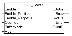
MC_Power activates software enable for an axis. Enable can be activated for both directions of travel or only one direction. At Status output operational readiness of the axis is indicated.
A velocity override influences the velocity of all travel commands by a specified percentage.
 | In addition to software enable it may be necessary to activate a hardware enable signal in order to enable a drive. This signal is not influenced by MC_Power and must be activated separately by the PLC. Depending on the drive type, Status also signals operational readiness of the drive. Digital drives provide feedback on operational readiness, while analog drives are unable to indicate their operational readiness. In the latter case Status only indicated operational readiness of the control side. |
Inputs
VAR_INPUT
    Enable          : BOOL; (* B *)
    Enable_Positive : BOOL; (* E *)
    Enable_Negative : BOOL; (* E *)
    Override        : LREAL (* V *) := 100.0; (* in percent - Beckhoff proprietary input *)
    BufferMode      : MC_BufferMode; (* V *)
END_VAR
Enable | General software enable for the axis. |
Enable_Positive | Feed enable in positive direction. Only takes effect if Enable = TRUE. |
Enable_Negative | Feed enable in negative direction. Only takes effect if Enable = TRUE. |
Override | Velocity override in % for all movement commands. (0 ≤Override≤ 100.0) |
BufferMode | The BufferMode is evaluated if Enable is reset. MC_Aborting mode leads to immediate deactivation of the axis enable. Otherwise, e.g. in MC_Buffered mode, the function block waits until the axis no longer executes a command. |
Outputs
VAR_OUTPUT
    Status    : BOOL; (* B *)
    Busy      : BOOL; (* V *)
    Active    : BOOL; (* V *)
    Error     : BOOL; (* B *)
    ErrorID   : UDINT; (* E *)
END_VAR
Status | Status=TRUE indicates that the axis is ready for operation. |
Busy | The Busy output is TRUE, as long as the function block is called up with Enable = TRUE |
Active | Active indicates that the command is executed. |
Error | Becomes TRUE if an error occurs. |
ErrorID | If the error output is set, this parameter supplies the error number |
Inputs/outputs
VAR_IN_OUT
    Axis     : AXIS_REF;
END_VAR
Axis | Axis data structure |
The axis data structure of type AXIS_REF addresses an axis unambiguously within the system. Among other parameters it contains the current axis status, including position, velocity or error state.