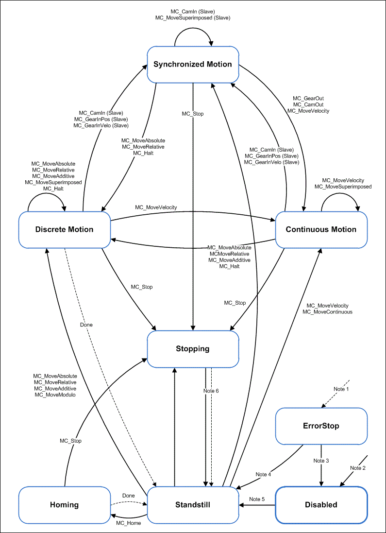
State diagram
The following state diagram defines the behavior of an axis in situations where several function blocks are simultaneously active for this axis. The combination of several function blocks is useful for generating more complex motion profiles or for dealing with exceptional situations during program execution.
|
Note 1 |
From any state in which an error occurs |
|
Note 2 |
From any state if MC_Power.Enable = FALSE and the axis has no error |
|
Note 3 |
MC_Reset and MC_Power.Status = FALSE |
|
Note 4 |
MC_Reset and MC_Power.Status = TRUE and MC_Power.Enable = TRUE |
|
Note 5 |
MC_Power.Status = TRUE and MC_Power.Enable = TRUE |
|
Note 6 |
MC_Stop.Done= TRUE and MC_Stop.Execute = FALSE |
As a basic rule, travel commands are processed sequentially. All commands operate within this axis state diagram.
The axis is always in one of the defined states. Motion commands resulting in a transition change the axis state and, as a result, the motion profile. The state diagram is an abstraction layer that reflects the real axis state, comparable to the process image for I/O points. The axis state changes immediately when the command is issued.
The state diagram initially targets single axes. Multi-axis blocks such as MC_CamIn or MC_GearIn influence the states of several axes, which can always be traced back to individual axis states of the axes involved in the process. For example, a cam plate master can be in Continous Motion state, while the associated slave is in Synchronized Motion state. Coupling of a slave has no influence on the state of the master.
The Disabled state is the default state of an axis. In this state can the axis cannot be moved through a function block. If the MC_Power block is called with Enable=TRUE, the axis changes to state Standstill or, on error, ErrorStop. If MC_Power is called with Enable=FALSE, the state changes to Disabled
The purpose of status ErrorStop is to stop the axis and then block further commands, until a reset was triggered. The Error state transition only refers to actual axis errors, not function block execution errors. Axis errors may also be indicated at the error output of a function block.
Function blocks that are not listed in the state diagram have no influence on the axis state. (MC_ReadStatus; MC_ReadAxisError; MC_ReadParameter; MC_ReadBoolParameter; MC_WriteParameter; MC_WriteBoolParameter; MC_ReadActualPosition and MC_CamTableSelect.)
The Stopping state indicates that the axis is in a stop ramp. Once the axis has stopped the state changes to StandStill.
Travel commands such as MC_MoveAbsolute that lead out of the Synchronized Motion state are possible only if they are explicitly permitted in the axis parameters. Uncoupling commands such as MC_GearOut are possible independent of that.