Integration in TwinCAT (CX9020)
This program shows the use of the individual function blocks in 5 examples 
The communication runs via a K-bus terminal.
Hardware
Setting up the components
The following hardware is required:
- 1x CX9020 Embedded-PC
- 1x KL1408 eight-channel digital input terminal for the execution of the individual tests.
- 1x KL6041 serial RS485 terminal
- 1x KL9010 end terminal
Software
PLC program
The respective test program section can be selected by setting the iTest variable in the MAIN program to values from 1 to 5.
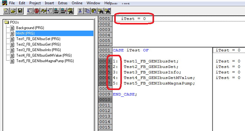
In the respective program sections, function blocks are then prepared that you can operate via the test inputs ib1 to ib8:
VAR_GLOBAL
   ib1     AT %I* : BOOL;
   ib2     AT %I* : BOOL;
   ib3     AT %I* : BOOL;
   ib4     AT %I* : BOOL;
   ib5     AT %I* : BOOL;
   ib6     AT %I* : BOOL;
   ib7     AT %I* : BOOL;
   ib8     AT %I* : BOOL;

   stInData    AT %I* : ST_GENIbusInData;
   stOutData   AT %Q* : ST_GENIbusOutData;
   stCommandBuffer    : ST_GENIbusCommandBuffer;
END_VAR
ib1..ib8: Pushbutton switch inputs for the tests.
stInData: Structure with the input variables for various terminal types.
stOutData: Structure with the output variables for various terminal types.
stCommandBuffer: Reference to the structure for communication (buffer) with the FB_GENIbusCommunication() function block.
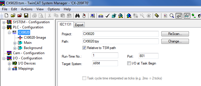
TwinCAT System Manager
In the TwinCAT System Manager the variables are already linked and assigned to the two tasks (Background: fast for communication, Main: slower for application).
Compile the PLC program and read it into the TwinCAT System Manager:
In accordance with these instructions, check whether the variable assignment is correct and that the variables have been linked.
After that you can start the TwinCAT System Manager and load and start the PLC program.