State diagram
The following state diagram defines the behavior of an axis.
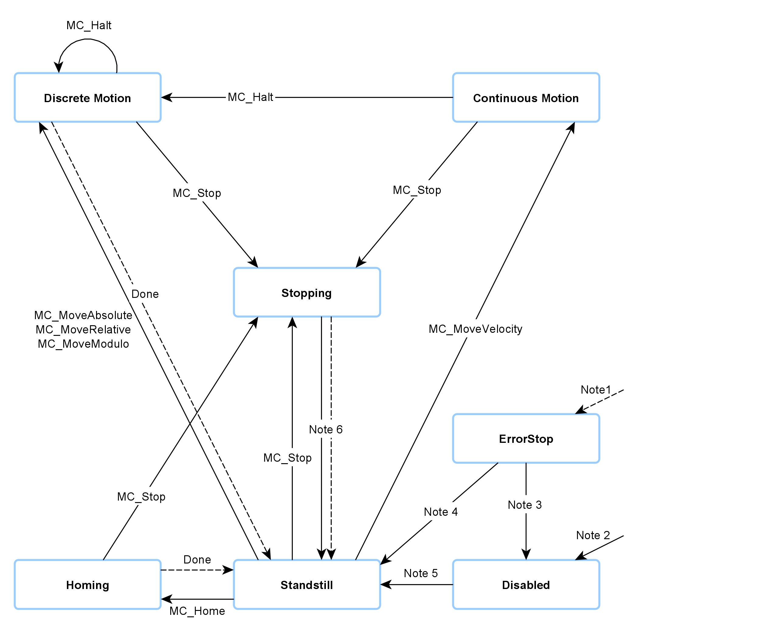
Note 1 | From undefined state in which an error occurs. |
Note 2 | From undefined state if MC_Power.Enable = FALSE. The axis has no fault. |
Note 3 | MC_Reset and MC_Power.Status = FALSE |
Note 4 | MC_Reset and MC_Power.Status = TRUE and MC_Power.Enable = TRUE |
Note 5 | MC_Power.Status = TRUE and MC_Power.Enable = TRUE |
Note 6 | MC_Stop.Done = TRUE and MC_Stop.Execute = FALSE |
Motion commands are always processed sequentially. All commands operate in the described state diagram.
The axis is always in one of the defined states. Each motion command that causes a transition changes the state of the axis and thus the motion profile. The state diagram is an abstraction layer that reflects the real axis state, comparable to the process image for I/O points. The axis state changes immediately when the command is issued.
The state diagram refers to single axes.
The "Disabled" state is the default state of an axis. In this state can the axis cannot be moved through a function block. When the MC_Power function block is called with Enable = TRUE, the axis changes to the "Standstill" state or, in the event of an error, to "ErrorStop" state. If the function block MC_Power is called with Enable = FALSE, the status changes to "Disabled".
The purpose of "ErrorStop" state is to stop the axis and then block further commands, until a reset was triggered. The "Error" state transition only refers to actual axis errors and not to execution errors of a function block. Axis errors can also be displayed at the error output of a function block.
Function blocks that are not listed in the state diagram influence the status of the axis.
The "Stopping" state indicates that the axis is in a stop ramp. After the complete stop the state does not change to "Standstill" until MC_Stop is called with Execute = FALSE. Otherwise the axis remains locked for further motion commands.