DCF77_TIME_EX
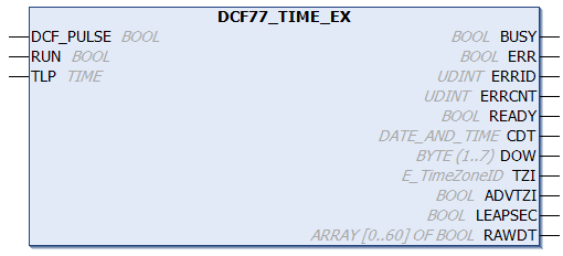
The function block "DCF77_TIME_EX" can be used to decode the DCF-77 radio clock signal. In contrast to the "DCF77_TIME" function block, this block checks two consecutive telegrams for plausibility as standard.
A rising edge at the RUN input starts the decoding process, which continues as long as the RUN input remains set. In the worst case synchronization of the function block takes up to one minute and two further minutes for decoding data for the next minute. During this time, the missing 59th second marker is waited for. Internally the function block is sampling the DCF-77 signal. In order to be able to sample the edges without error the function block should be called once in each PLC cycle. Satisfactory results can be obtained with a cycle time of <= 25 ms. In case of a missing or faulty DCF-77 signal, the ERR output is set to TRUE and a corresponding error code is set at the ERRID output. The ERR and ERRID outputs are reset the next time a correct signal is received. Some receivers provide an inverted DCF-77 signal. In such cases the signal must first be inverted before being passed to the DCF_PULSE input. When operating without errors, the current time is updated at the CDT output every minute. Thereby the READY output is set to TRUE for one cycle of the PLC at the zeroth second. At this time the DCF-77 time at the CDT output is valid, and can be evaluated by the PLC program. The READY output is only set if it was possible to receive the data for the coming minute without errors. The transferred parity bits are used for fault detection, and the last two telegrams are checked for plausibility. In the event of poor reception conditions, 100% error-free detection cannot be guaranteed. I.e. with two faulty (inverted) bits in two subsequent telegrams, the function block cannot detect an error and also sets the READY output to TRUE. Due to the plausibility check the probability of the appropriate bits becoming distorted, thereby preventing detection of such an error, is quite small.
Errors that occur during reception are registered by the function block. The ERRCNT output is an error counter. This counter indicates the number of errors that have occurred since the last correctly received signal. The counter is reset the next time a signal is correctly received.
Time code
During each minute, the numbers that encode the year, month, day, day of the week, hour and minute are transmitted in BCD format through pulse modulation of the second marks. The transmitted information always describes the subsequent minute. A second marker is transmitted each second. A second marker with a duration of 0.1 s represents a binary zero, while a duration of 0.2 s represents binary one. The information is extended with 3 check bits. At the 59th second, and a receiver can use this "gap" to synchronize itself.
 Inputs
VAR_INPUT
    DCF_PULSE  : BOOL;
    RUN        : BOOL;
    TLP        : TIME := T#140ms;
END_VAR
Name | Type | Description |
|---|---|---|
DCF_PULSE | BOOL | The DCF-77 signal. |
RUN | BOOL | A rising edge at this input initializes the function block and starts decoding the DCF-77 signal. If this input is reset, the decoding process is stopped. |
TLP | TIME | Via this input a fixed limit is set for differentiating between zero and one, depending on the recipient specification. If the signal is poor the pulse widths are smaller. |
TLP specifications
The receiver specifications usually contain information about the minimum and maximum pulse for the two logic signals, with the higher value expected for higher field strengths and the lower value for low field strengths or in the event of interference. Problems may also occur near the sender (where the field strength is very large) if the pulse width of the logic zero becomes excessive. Check the specification of the receiver used and configure the pulse length accordingly.
E.g.: in the specification of Atmel T4227 (Time Code Receiver) the following pulse length is given:
100 ms pulse (zero): min: 70 ms, typical: 95 ms, max: 130 ms
200 ms pulse (one): min. 170 ms, typical 195 ms, max. 235 ms
For this IC a limit value of 150 ms would be optimal = 130 + ( ( 170 ms - 130 ms ) / 2 ).
 | If the configured limit value for the pulse length is too small, short pulses are detected as long. Conversely, if the configured limit value is too big, long pulses are detected as short. If the checksum is correct, the receiver cannot detect these errors. In the first case the receiver may supply times that are in future range, in the second case the times may be in the past. |
 Outputs
VAR_OUTPUT
    BUSY    : BOOL;
    ERR     : BOOL;
    ERRID   : UDINT;
    ERRCNT  : UDINT;
    READY   : BOOL;
    CDT     : DATE_AND_TIME;
    DOW     : BYTE(1..7);(* ISO 8601 day of week: 1 = Monday.. 7 = Sunday *)
    TZI     : E_TimeZoneID;(* time zone information *)
    ADVTZI  : BOOL;(* MEZ->MESZ or MESZ->MEZ time change notification *)
    LEAPSEC : BOOL;(* TRUE = Leap second *)
    RAWDT   : ARRAY[0..60] OF BOOL;(* Raw decoded data bits *)
END_VAR
Name | Type | Description |
|---|---|---|
BUSY | BOOL | This output is set when the function block is activated. |
ERR | BOOL | This output is set when an error occurs in the decoding. |
ERRID | UDINT | If the ERR output is set, this parameter supplies the error number. |
ERRCNT | UDINT | The number of errors that have occurred since the last correctly received signal. |
READY | BOOL | If this output is set, the data at the CDT output is valid. |
CDT | DATE_AND_TIME | The DCF-77 time in DATE_AND_TIME format. |
DOW | BYTE | Day of the week according to ISO 8601: 1 = Monday... 7 = Sunday |
TZI | E_TimeZoneID | Time zone information (summer/winter time) |
ADVTZI | BOOL | Summer/winter time changeover notification, e.g. CET -> CEST or CEST -> CET. The changeover between CEST/CET occurs at the end of this hour (see telegram examples). |
LEAPSEC | BOOL | Leap second notification. A leap second is added at the end of this hour (see telegram examples). |
RAWDT | ARRAY[0..60] OF BOOL | Last decoded (raw) bit information. Please ensure that only the parity bits of the time information are checked. The parity bits of the weather data are not analyzed! |
|
Error Codes |
Error description |
|---|---|
|
0 |
No error |
|
0x100 |
Timeout error. Possibly because no DCF-77 signal is detected. |
|
0x200 |
Parity error. Incorrect bits were detected in the received data. |
|
0x300 |
Incorrect data was received. Since the parity check can only detect one incorrect bit, the received data is checked again for validity (this error code will be generated, for instance, if month = 13). |
|
0x400 |
The last decoding cycle was too long. This error can occur when reception is poor (not enough second markers were received). |
|
0x500 |
The last decoding cycle was too short. This error can occur when reception is poor (additional edges were received). |
Telegram examples:
Example:
If data are received error-free, a TwinCAT software clock (RTC) is synchronized with the radio time in the sample application.
PROGRAM MAIN
VAR
    bDcfPulse AT%I* : BOOL;
    fbDcf           : DCF77_TIME_EX;
    bBusy           : BOOL;
    bError          : BOOL;
    nErrID          : UDINT;
    nErrCnt         : UDINT;
    bDcfValid       : BOOL;
    tDcfDt          : DT;
    nDow            : BYTE(1..7);
    eTzi            : E_TimeZoneID;(* time zone information *)
    bAdvTzi         : BOOL;(* MEZ->MESZ or MESZ->MEZ time change notification *)
    bLeapSec        : BOOL;(* TRUE = Leap second *)
    arRawDt         : ARRAY[0..60] OF BOOL;
    fbRtc           : RTC;
    bRtcValid       : BOOL;
    tRtcDt          : DT;
END_VAR
fbDcf( DCF_PULSE:= NOT bDcfPulse, RUN:= TRUE, TLP:= T#140MS,
BUSY=>bBusy, ERR=>bError, ERRID=>nErrID, ERRCNT=>nErrCnt,
READY=>bDcfValid, CDT=>tDcfDt, DOW=>nDow, TZI=>eTzi,
ADVTZI=>bAdvTzi, LEAPSEC=>bLeapSec, RAWDT=>arRawDt );
fbRtc( EN := bDcfValid, PDT := tDcfDt, Q=>bRtcValid, CDT=>tRtcDt );Online View:
See also description of the DCF77_TIME function block.
Requirements
Development environment | Target platform | PLC libraries to be integrated (category group) |
|---|---|---|
TwinCAT v3.1.0 | PC or CX (x86, x64, Arm®) | Tc2_Utilities (System) |