Delta Type 1
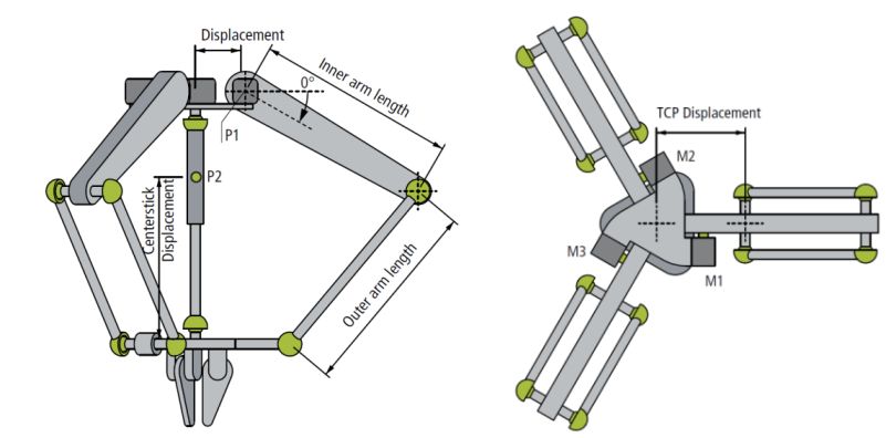
The delta kinematics type 1 is built up as shown in the schema above. The kinematic transformation expects ball joints (or elements with the same behavior) in the connection of the arms and to the lower plate.
Optionally the center stick for the orientation of the gripper can be parameterized.
All motor axes are scaled in degree and 0° is defined as shown in the schema with positive direction in direction of the arrow. That is for all 3 motors the same.
Parameter for kinematics
|
Parameter |
Description |
Unit |
|---|---|---|
|
InnerArmLength |
Length from pivot point to pivot point of the inner arm. That is the arm which is directly linked to the motor |
mm |
|
OuterArmLength |
Length from pivot point to pivot point of the outer arm. |
mm |
|
Displacement |
Length from center of the ground plate to the virtual rotary axes of the inner arm |
mm |
|
TcpDisplacement |
Length from center of the gripper plate to the virtual rotary axes of the outer arm |
mm |
|
MCS2WCS OID |
Object ID of a static transformation which defines the position of MCS in base coordinate system (normally WCS). |
|
Parameter for dynamic model
|
Parameter |
Description |
Unit |
|---|---|---|
|
InnerArmMass |
Total mass of the inner arm |
kg |
|
InnerArmMomentOfInertia |
Moment of inertia of the inner arm related to the turning point P1 that is connected to the motor |
kg mm^2 |
|
OuterArmMass |
Mass of the outer arm. If there are 2 rods the total mass is required. Optionally the link mass can described in an own parameter |
kg |
|
LinkMass |
Mass of the link that connects inner and outer arm. Can be used if the link mass is not yet included to outer and inner arms. |
kg |
|
TcpMass |
Mass of the tool center point including gripper plate and gripper. The payload is usually written to a separate parameter. |
kg |
|
CenterStickMass |
Total mass of the center stick |
kg |
|
CenterStickMomentOfInertia |
Moment of inertia of the center stick related to the center of gravity (P2) |
kg mm^2 |
|
CenterStickCenterOfMassDisplacement |
Length from gripper plate to center of gravity of the stick. |
mm |
|
FirstDriveTorqueOID |
Object ID of the first drive torque |
|
|
SecondDriveTorqueOID |
Object ID of the second drive torque |
|
|
ThirdDriveTorqueOID |
Object ID of the third drive torque |
|
|
GravityOrientationOID |
Object ID of a static transformation that describes the mounting orientation. This parameter is used if the gripper does not show to the ground. The static transformation’s Z-axis defines the gravity orientation. If the robot is mounted as shown in the picture this OID can be zero. |
|
Required Product Level:
Level 3