2-D-Kinematics Type 3
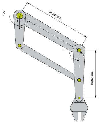
The 2-D-kinematics type 3 is built up as shown in the schema above.
All motor axes are scaled in degree and 0° is defined as shown in the schema with positive direction in direction of the arrow.
This kinematic type is implemented as left handed. The shaft of motor 1 & 2 are located in the origin of the coordinate system.
Parameter for kinematics
|
Parameter |
Description |
Unit |
|---|---|---|
|
InnerArmLength |
Length from motor shaft to pivot point of the outer arm. |
mm |
|
OuterArmLength |
Length from pivot point to tool center point of the outer arm. |
mm |
|
MCS2WCS OID |
Object ID of a static transformation which defines the position of MCS in base coordinate system (normally WCS). |
|
Parameter for dynamic model
|
Parameter |
Description |
Unit |
|---|---|---|
|
InnerArmMass |
Total mass of the inner arm |
kg |
|
OuterArmMass |
Mass of the outer arm. |
kg |
|
ToolCenterpointMass |
Mass of the tool center point including gripper plate and gripper. The payload is usually written to a separate parameter. |
kg |
|
FirstDriveTorqueOID |
Object ID of the first drive torque |
|
|
SecondDriveTorqueOID |
Object ID of the second drive torque |
|
|
GravityOrientationOID |
Object ID of a static transformation that describes the mounting orientation. This parameter is used if the gripper does not show to the ground. The static transformation’s Z-axis defines the gravity orientation. If the robot is mounted as shown in the picture this OID can be zero. |
|
Required Product Level:
Level 2