Configuration
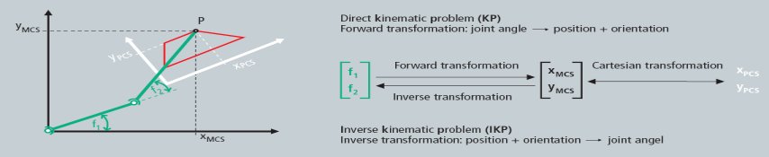
Based on the PLCopen we distinguish two main coordinate systems:
- Axis Coordinate System (ACS)
The axes of the ACS are connected to the real motor. So this coordinate system represents the positioning of the motor without taking care about the position of the tool center point (TCP). - Machine Coordinate System (MCS)
this is by default a Cartesian coordinate system. Programming of movements are usually done here and therefore the axes X, Y, and Z are used. The backward transformation is calculating the positions for the axes coordinate system. The axes in MCS are pure software axes and of type simulation encoder.
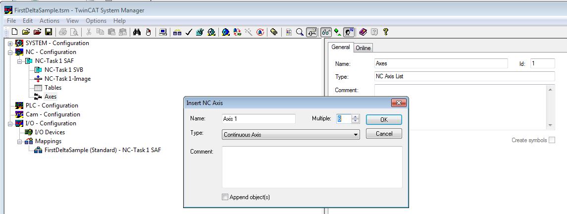
All ACS and MCS axes that are used in a kinematic transformation channel must be created in the System Manager. So for example a Delta-Robot will have 3 ACS axes (M1...M3) and 3 MCS axes (X, Y, Z).
Configure Kinematic Transformation Channel
- 1. Append all axes (ACS and MCS) to the NC-Configuration in System Manager equal to PTP axes.
- 2. Append a kinematic channel to the System Manager configuration.
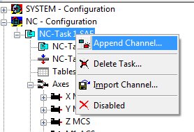
- Appending a channel creates an instance of the kinematic group.
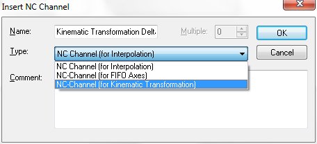
- 3. Select the channel type: NC-Channel (for Kinematic Transformation) to run a kinematic transformation.
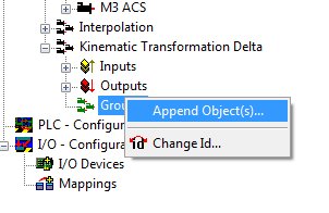
- 4. Append the objects under the group that represent the user’s kinematic configuration.
- 5. Browse for TcNcKin.tmc in TwinCAT\IO-Folder.
- 6. To start-up for instance the transformation for a delta-robot select
- Delta Type 1
- Static-Trafo 6D (optional MCS shift)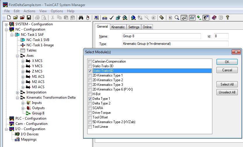
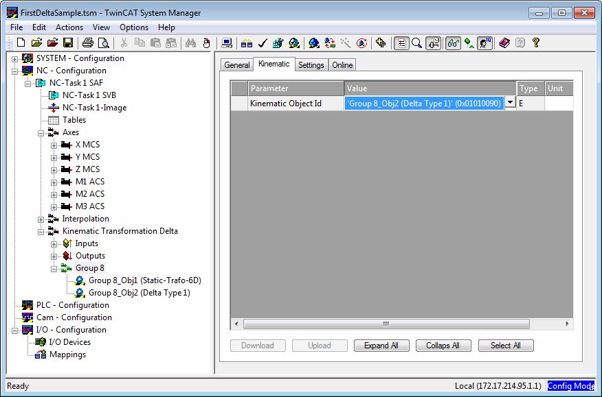
- 7. The transformation group has to know what root module has to be called. Therefore the object ID of the kinematics (in this case Delta Type1) must be selected. The kinematic object defines the number of ACS and MCS axes to be used in PLC (cf. ST_KinAxes).
- 8. Parameterize the objects parameters to the used kinematics.
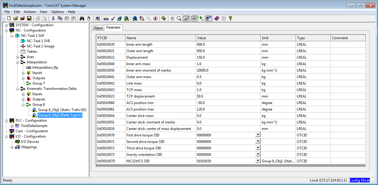
- After this the System Manager configuration is done.
- 9. The Transformation can now be activated from PLC (cf. Plc Library). To address the transformation define a cyclical channel interface in the PLC and link it to the kinematic channel’s I/O.
in_stKinToPlc      AT %I*     : NciChannelToPlc;
out_stPlcToKin     AT %Q*     : NciChannelFromPlc;