Auxiliary function for the calculation of motion limits within a workpiece coordinate system
With the following command the limits of a motion in the current workpiece coordinate system (WCS) are calculated in the direction of a programmed motion vector with the components VC1, VC2, VC3. The vector components have not been programmed in standardized form. The axes specific software limit switches are basis for the traverse limiting. Based on these values the control calculates the motion limits in the current coordinate system.
#GET WCS POSLIMIT [VC1=<Vectorcomp.1> VC2=<Vectorcomp. 2> VC3=<Vectorcomp.3>]With the following global variables, the result of the calculation can be read out for the first three axes of the coordinate system.
V.G.WCS_POSLIMIT_1 Motion limit in the first main axis in WCS
V.G.WCS_POSLIMIT_2 Motion limit in the second main axis in WCS
V.G.WCS_POSLIMIT_3 Motion limit in the third main axis in WCS
Notice | |
The programmed motion direction has absolutely to be kept during the real executed motion, otherwise the calculated motion limits are wrong! |
Programming example
N05...
N10 G98 X-100 Y-100 Z-100 (Shifting of negative software limits)
N20 G99 X200 Y200 Z300 (Shifting of positive software limits)
N30 #ECS ON (Selection of effector coordinate system)
N40 #GET WCS POSLIMIT [VC1=0 VC2=0 VC3=1] (Calculation of WCS limit)
N50 G01 G90 Z=V.G.WCS_POSLIMIT_3 F2000 (Move to WCS limit in Z)
N60 #ECS OFF (Deselection of effector coordinate system)
N70...
Example for correct use of the command
N05...
N10 #CS ON[0,0,0,0,0,45]
N20 #GET WCS POSLIMIT [VC1=1 VC2=1 VC3=0]
N25 G01 G90 F2000
N30 X=V.G.WCS_POSLIMIT_1 Y=V.G.WCS_POSLIMIT_2 Z=V.G.WCS_POSLIMIT_3
N40 #CS OFF
N50...
Wrong, resulting motion direction not corresponding to setting:
N05...
N10 #CS ON[0,0,0,0,0,45]
N20 #GET WCS POSLIMIT [VC1=1 VC2=1 VC3=0]
N25 G01 G90 F2000
N30 X=V.G.WCS_POSLIMIT_1 Y=V.G.WCS_POSLIMIT_2
N40 Z=V.G.WCS_POSLIMIT_3
N50... 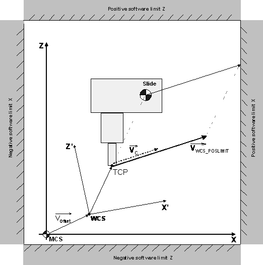 Fig.112: Example for motion limits in ZX plane in the current WCS