Dynamically optimized contouring (Type 6)
So far, the polynomial contouring types 1-5 define a direction- and curvature-continuous connection of two traverse blocks. With reference to the axes the contour curve possibly leads to a fluctuation of acceleration.
During the axis related consideration of the dynamic data (acceleration, jerk) the contouring curve is determined with a steady acceleration (minimum jerk) of the involved axes. By using the maximum acceleration of the axes additionally the duration of the contouring is reduced.
The parametering is done with the following statement:
#CONTOUR MODE [ DIST_SOFT [PATH_DIST<expr>] [TRACK_DIST<expr>]
[ACC_MAX<expr>] [ACC_MIN<expr>] [RAMP_TIME<expr>]
[DIST_WEIGTH<expr>] ]
DIST_SOFT Dynamic optimized contouring
PATH_DIST<expr> Corner distance of pre and post block (symmetric) in mm or degree, from which the deviation from original contour is allowed. The definition is related to the travel distance of the feed axes.
Default value: 1 mm or 1 °
Monitoring off: -1 mm or -1 °
TRACK_DIST<expr> Corner distance of pre and post block (symmetric) in mm or degree, from which the deviation of the non-feed axes (dragged axes) from original contour is allowed.
Default value: Value is mapped automatically from PATH_DIST, as long as this value has not been explicitly defined (since program start).
Monitoring off: -1 mm or -1 °
ACC_MAX<expr> Amount in percent of maximum acceleration (machine data), which could be used by contour.
Default value: 100 %
ACC_MIN<expr> Amount in percent [0; 100] of maximum acceleration (machine data), which shall be used by contour. If this acceleration is to less to keep to the given corner distance (see SYM_SIST), the used acceleration is increased up to the maximum value (ACC_MAX).
Default value: 50 %
RAMP_TIME<expr> Percentage weighting of the ramp time [ 0; 10000].
Default value: 100 %
DIST_WEIGHT<expr> Percentage weighting of the corner distances in proportion to the previous / following block [ 0; 100].
Default value: 0 %
Restrictions:
- The dynamical optimized contouring is possible for linear block transitions. If any circular block is included in the transition, the calculation is switched to the standard corner distance calculation (without dynamic optimization, according to Type 3).
- For the calculation only one ramp time of each axis is used (maximum value of the individual ramp times).
- No cinematic transformations are considered. If any transformation is active the calculation also switches automatically to the standard mode (according to Type 3).
In many cases the weighting of the corner distances by the parameter DIST_WEIGHT depending on the previous / following block results in an optimized utilization of the available block length.
During the axis specific contouring the corner distances of the previous and the following block basically are identical (symmetrical). If in addition the maximum corner distances are limited on the half block travel distance, for longer travel distances with shorter previous/ following travel distances the result is a smaller contouring zone and a smaller contouring velocity.
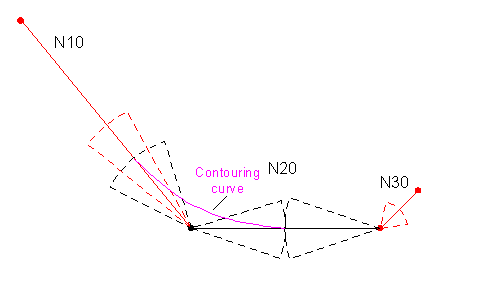 Fig.45: Maximum corner distance of block N20 independent from block length of N10 and N20 (DIST_WEIGHT = 0 %)
If the length of the previous and the following block are considered for the calculation of the maximum corner distances, the contouring zone can be increased.
 Fig.46: Maximum corner distance of block N20 subdivided in the ratio of the block length of N10 and N30 (DIST_WEIGHT = 100 %)
Programming example
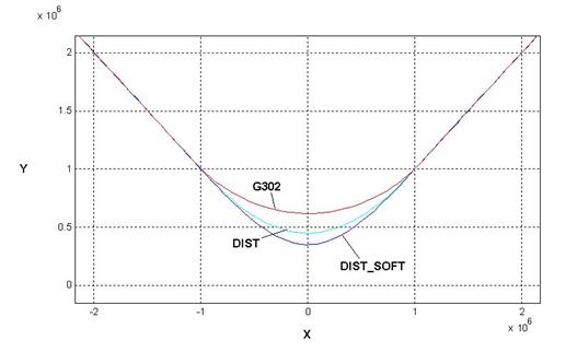
Comparison of contouring of a one-quarter (90°) corner with the methods:
- Explicit inserting of a radius (G302):
P1 = 150 (Eckenabstand
P4 = 2000 (Anfahrposition
N10 X-P4 YP4
N20 X0 Y0
N25 G302 IP1
N30 XP4 YP4
N40 M30 - Conventional contouring with definition of corner distance (DIST):
#SET SLOPE PROFIL[1]
P1 = 150 (Eckenabstand
P4 = 2000 (Anfahrposition
#CONTOUR MODE [DIST PRE_DIST=P1 POST_DIST=P1]
N10 X-P4 YP4
N20 X0 Y0 G61
N30 XP4 YP4
N40 M30 - Dynamically optimized contouring (DIST_SOFT):
#SET SLOPE PROFIL[1]
P1 = 150 (Eckenabstand
P4 = 2000 (Anfahrposition
#CONTOUR MODE [DIST_SOFT PATH_DIST=P1 ACC_MAX=100 ACC_MIN=50 RAMP_TIME=100]
N10 X-P4 YP4
N20 X0 Y0 G61
N30 XP4 YP4
N40 M30
Comparison of all three modes in position: