Mirroring with axis information (G351)
The G-functions G20 to G23 that are freely available in conformity with DIN 66025 have been used for mirroring [2]. The following extended syntax offers the possibility, to programm explicitly the axes for mirroring.
G351 <axis_name> [ [+] | - ] 1 { <axis_name> [ [+] | - ] 1 } (non-modal)G351 Axis-specific selection of mirroring. The G-function G351 is non modal, but mirroring is modal for an axis programmed with this function.
<axis_name> A coordinate consists of an address letter followed by a mathematical expression based on which the coordinate value is calculated.
Coordinate value -1: Selects mirroring
Coordinate value 1 or +1: Cancels mirroring
Programming example
G351 X-1 Y1 Z+1 (Selects mirroring of the X axis and cancels mirroring)
(of the Y and Z axes)- The axes to be mirrored can be programmed anywhere in the NC-block.
- At least one axis coordinate must be programmed together with G351.
- The function G351 must be programmed on its own in the NC-block. The block number N is an exception to this rule
- Repeated selection or cancellation of mirroring of an axis is permissible. However, an error message is output in the event of repeated programming in the same NC block.
- If mirroring is selected in synchronous operation for the leading axis (master axis), mirroring is not automatically also selected for the trailed axis (slave axis). However, the slave axis is always trailed according to the travel movements of the master axis. An additional travel movement as the result of mirroring of the master axis therefore always influences the slave axis.
- Mirroring is canceled for all axes at program start and reset. When axes are exchanged, mirroring of the changed axis is canceled.
- Mirroring of the first or second main axis influences the direction of travel during circular interpolation and tool radius compensation.
- When mirroring is programmed with active tool radius compensation, the selected side of (G41/G42) is swapped automatically by the Decoder. This is only allowed for linear blocks. This behavior is firmly given by the control manufacturer.
 Fig.28: Mirroring of the selected side during active tool radius compensation
- If a reference point offset is programmed for a mirrored axis, the coordinates for the reference point offset are also mirrored. When mirroring of an axis is selected or canceled, the reference point offset is also mirrored.
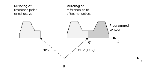 Fig.29: Mirroring of reference point offset
- The coordinates of circle center point I, J, K are also mirrored (Chapter "Mirroring (G21/G22/G23/G20)")
- For the insertion of chamfers and rounding (G301/G302) the I-string is used to enter the value of the chamfer or rounding. Therefore, mirroring has not to be considered here.
- G21 to G23 only select mirroring for the first two main axes regardless of the axis designation.
- G20 only cancels mirroring of the first two main axes.
The following example shows how to use the G351 function. Let us assume that the axes X, Y and Z are the first, second and third main axes here.
Programming example
N10 G351 X-1 (Selects mirroring of the X axis (G21))
N20 G351 Y-1 (Selects mirroring of the Y axis (G22))
N30 G351 X-1 Y-1 (Selects mirroring of the X and Y axes (G23))
N40 G351 X1 Y+1 (Cancels mirroring of the X and Y axes (G20))
N50 X1 G351 Y-1 Z1 (Selects mirroring of the Y axis and cancels)
(mirroring of the X and Z axes)