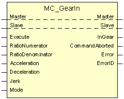
MC_GearIn
The MC_GearIn FB commands gear coupling with a gear ratio. The gear ratio defines the speed ratio between the master and slave axes. The synchronization to the velocity is jerk-limited. ‘Jerk’ is set via input at the FB.
The slave axis can be coupled either to master setpoints or to actual master values. The selection is made in the ‘Mode’ input parameter.
For test purposes, automatic phase compensation has also been implemented. This function is also activated via the ‘Mode’ parameter. After speed synchronization (actual value or setpoint coupling), automatic phase compensation between the master and slave takes place based on the two axes' actual positions. Now, a phase offset unequal to ‘0’ cannot be set, i.e. for sensible synchronization the master and slave coordinate systems must have the same origin. Alternatively, the PLC programmer must explicitly establish position synchronicity by calling up MC_MoveSuperImposed.
If possible, automatic phase compensation should be used only for testing, but not for operation on a system. However, the behavior of the respective axis mode combination must be exactly observed.
The following behavior during automatic phasing results for the various axis modes of the master and slave:
- Master linear, slave linear Phase compensation is realized at the zero master/slave offset
- Master modulo, slave modulo Phase compensation is realized at the zero master/slave offset over the shortest distance. The master and slave should best have the same modulo range. If this is not the case, the modulo range of the master axis is used to determine the distance.
- Master modulo, slave linear Phase compensation is realized at the zero master/slave offset The distance is not modulo calculated.
- Master modulo, slave modulo Phase compensation is realized at the zero master/slave offset The distance is not modulo calculated (because the modulo range of the master axis is (+231-1) to (-231)).
Block diagram
Parameters of the FB
VAR_IN_OUT | ||||
| Master | AXIS_REF | Axis reference to the master axis. | |
| Slave | AXIS_REF | Axis reference to the slave axis | |
VAR_INPUT | ||||
| Execute | BOOL | Start the gearing process at the rising edge. | |
| RatioNumerator | DINT | Gear ratio Numerator. | |
| RatioDenominator | DINT | Gear ratio Denominator. | |
| Acceleration | LREAL | Acceleration for gearing in (always positive). Range [1.0, 2147483647.0] | |
| Deceleration | LREAL | Deceleration for gearing in (always positive). Range [1.0, 2147483647.0] | |
| Jerk | LREAL | Jerk for gearing in (always positive). Range [1.0, 2147483647.0] | |
| Mode | UDINT | Possible values are:see ‘Extracted nested table 1’ | |
0: (16#0) | Type of coupling between master axis and slave: Coupling based on command Automatic phase compensation: off. | |||
128: (16#80) | Type of coupling between master axis and slave: Coupling based on actual values. | |||
256: (16#100) | Automatic phase compensation: on. Only for testing purposes! | |||
VAR_OUTPUT | ||||
| InGear | BOOL | Commanded gearing completed. | |
| Error | BOOL | Indicates if an error has occurred. | |
| ErrorID | WORD | Error identification. | |
| CommandAborted | BOOL | Command is aborted by another command. | |
Behavior of the FB
- The command for gear coupling can only be issued only when the slave axis is in the ‘Standstill’ or ‘Continuous Motion’ or ‘Discrete Motion’ or ‘Synchronized Motion’ state. If this is not the case, the ‘Error’ output is set to FALSE and ‘ErrorID’ indicates an error value that designates the state the axis is currently in.
- The value range of the ‘Acceleration’, ‘Deceleration’ and ‘Jerk’ input variables is monitored and, if it is exceeded, an error number referring to the variable is output at the ‘ErrorID’ output and ‘Error’ is set to TRUE. The ‘RatioDenominator’ input variable is the denominator of the gear ratio, and this is why this must be unequal to 0. In the event of the ‘RatioDenominator’ = 0 error, the ‘ErrorID’ 44040 (ERR_PO_AX_RATIO_DENOM_ZERO) is output and ‘Error’ becomes TRUE.
- Values that correspond to a minimum ramp time of TA (cycle time of the IPO, e.g. 2 ms) and a maximum ramp time of 100s make sense as the ‘Jerk’. The limit transition to non-jerk-limited speed realization lies at the minimum ramp time of TA. In the case of a value of 0, the maximum ramp time from the axis MDS is used to determine the ‘Jerk’.
- The function block is re-triggerable. Therefore, it can send a command again in the active state.
- For an axis to work as a cam or gear ‘Master’ and for it to transfer the necessary synchronisation information to all axes (slaves) cyclically, the ‘cam_gear.is_master’ parameter must be set to 1 for such a master axis in the axis parameter configuration. An axis configured as the master can simultaneously also be coupled to another master axis as a slave.
- The MC_GearIn FB can be used for linear and rotatory slave axes. In the case of linear slave axes, software limit switch monitoring is active after homing. On deceleration to the software limit, the current limit ramp is used, and gear coupling is released.
- In all other situations, gear coupling is ‘holy’, i.e. axis-specific feed hold, axis-specific override CANNOT act on the cam slave because this would be contradictory to the coupling specification.
- The situation with Emergency Stop is similar: in the current realization, the MCE finds out about an Emergency Stop situation exclusively via the drive interface. In the event of Emergency Stop, the gear coupling is released and is decelerated with the current limit, which is entered in the achs_mds parameter: ‘getriebe[0].lslope_profil.a_grenz_stufe_1’. This standard behavior in the case of Emergency Stop can be rendered inactive with the ‘cam_gear.keep_coupling_on_lr_error’ parameter. Then gear coupling is ensured even in the event of Emergency Stop if the drive still follows the setpoints. The situation when the enable feed watchdog drops out is similar; this leads to an error for coupled slave axes because motion prevention has higher priority than gear coupling because this is a safety function. This standard behavior on dropping out of the feed enable watchdog can be rendered inactive with the ‘cam_gear.keep_coupling_on_fe_drop’ parameter. Then, gear coupling is ensured even in the event of the feed enable watchdog dropping out.
- With the ‘Mode’ input parameter, you can set whether master/slave coupling is to take place with the master's actual values or setpoints and whether automatic phasing is to take place after speed synchronisation.
Each SAI axis can be operated as a slave axis. The following standard axis parameters must be set in a slave axis for both actual value and setpoint coupling:
- cam_gear.v_diff_percent
- cam_gear.time_in_window
- cam_gear.time_out_in_window
- cam_gear.v_max_slave
- cam_gear.a_max_slave
- getriebe[0].vb_mit_null
In the case of actual value coupling, the following parameters must also be set in the slave axis:
Filtering of the master actual values
- cam_gear.mv_type Digital FIR filter on/off.
- cam_gear.mv_nbr_cycles Number of the values over which filtering takes place.
Dead time compensation for constant speed
- cam_gear.delay_time Dead time compensation ensures that constant speed and a coupling ratio of 1 always results in the same phase between the master and slave. Compensation involves errors in phases of speed that is not constant. The dead time should be determined by trial and error.
When automatic phasing is commanded (actual value or setpoint coupling), the following axis parameters must also be set in the slave:
- cam_gear.v_phasing ‘Speed’ of the superimposed motion for phasing.
- cam_gear.a_phasing ‘Acceleration’ of the superimposed motion for phasing.
- cam_gear.d_phasing ‘Deceleration’ of the superimposed motion for phasing.
- cam_gear.j_phasing ‘Jerk’ of the superimposed motion for phasing.