Use of MC_CamIn
‘MC_CamIn.startmode’
HLI_CI_RAMP_IN            : HLI_UNS32:= 16#00000001;
HLI_CI_ABSOLUTE           : HLI_UNS32:= 16#00000002;
HLI_CI_RELATIVE           : HLI_UNS32:= 16#00000004;
Ramp-In and Absolute are always used. This is why these three bits currently have no effect.
HLI_CI_LOCK_TABLE : HLI_UNS32:= 16#00000008;Specifies whether the table used for online value modification during coupling is locked. This should always be set for table data type to which atomic access is not possible. Otherwise, the problem of simultaneous memory access must be observed.
HLI_CI_F_PERIODIC : HLI_UNS32:= 16#00000010;If this flag is not set for MC_CamIn, the stored cam is run through exactly once per rising edge of ‘MC_CamIn.Execute’. Travel over the cam is synchronised to the modulo passing through of the master position. If the slave axis is not already on the start position of the cam table, the slave axis is drawn immediately to the cam's starting position at rising edge of ‘MC_CamIn.Execute’ and stays there until the master axis passes through zero the next time. From there, the cam profile is run through precisely once. If ‘MC_CamIn.Execute’ is triggered again during the cycle, the cam is run through a further time as if ‘periodic’ would be TRUE. Without re-triggering the slave axis is decoupled from the master axis at the end of the CAM-table. This means, that the slave axis is stopped immediately, if it is not in standstill already.
If the cam has been modelled for an endlessly rotating slave axis, in connection with the use of interpolation point interpolation (‘MC_CamIn.TableFctType’ = HLI_LINEAR or HLI_POLYNOM_3), it is necessary to specify in which direction modulo correction is to take place.
If the cam has been modelled so that it passed through the slave's modulo range in the positive direction, in ‘MC_CamIn.Startmode’ the bit:
HLI_CI_ENDLESS_POSITIVE : HLI_UNS32:= 16#0x00000020;must be ORed.
If the cam passes through the modulo range of the slave axis in the negative direction, in ‘MC_CamIn.startmode’ the bit:
HLI_CI_ENDLESS_NEGATIVE : HLI_UNS32:= 16#0x00000040;must be set.
The manufacturer-specific ‘MC_CamIn.table_fkt_type’ input to the PLCopen FB specifies how interpolation takes place between two table interpolation points:
HLI_STEP_DIRECT : HLI_UNS32 := 0;The position entry of the slave axis ssi is output within the position interval of the master axis smi, smi+1.
HLI_LINEAR : HLI_UNS32 := 1;Within the master axis position interval smi, smi+1, interpolation takes place in linear fashion between the slave position entries ssi, ssi+1.
HLI_POLYNOM_3 : HLI_UNS32 := 2;Within the master axis position interval smi, smi+1, a constant-tangent, cubic Bezier spline is interpolated between the four neighbouring slave axis position entries ssi-1,ssi, ssi+1, ssi+2. Polynomial coefficient calculation takes place online.
HLI_POLYNOM_3_KOEFF : HLI_UNS32 := 3;Within the position interval of the master axis smi, smi+1, the position entry of the slave axis ssi (line with four values ai) consists of the coefficients of a polynomial with the format
X = a0 + a1t + a2t2 + a3t3.
Polynomial coefficient calculation therefore takes place offline.
LINE_POLY5 : HLI_UNS32 := 4;Motion segments alternating between LINE and POLY5, starting with LINE
POLY5_LINE : HLI_UNS32 := 5;Motion segments alternating between LINE and POLY5, starting with POLY5
TABLE_DEFINED : HLI_UNS32 := 6;The interpolation type is defined within the table.
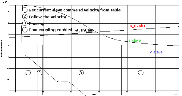
Behavior of MC_CamIn:
Both, when the master axis is already running and it is in ‘StandStill’, a so-called amplitude-true ramp-in takes place.
Engaging a cam on a running master shaft corresponds to the following mechanical analogy: The coupling has slip until the cam to be driven along with it is at the right speed. The cam is then brought to the right position.
The following parameters of achsmds.lis influence this behavior:
- cam_gear.v_diff_percent Speed tolerance in phase 2. Default: 10
- cam_gear.time_in_window Min. duration of phase 2. Default: 8000[µs]
- cam_gear.time_out_in_window Max. duration of phase 2. Default: 1000000[µs].
Synchronisation of the speed is jerk-limited. The ‘jerk’ value must be set in the ‘cam_gear.j_vel_sync’ parameter in the axis MDS. Values that correspond to a minimum ramp time of TA (cycle time of the IPO, e.g. 2 ms) and a maximum ramp time of 100s make sense as the ‘jerk’. The limit transition to non-jerk-limited speed realization lies at the minimum ramp time of TA. In the case of a value of 0, the maximum ramp time from the axis MDS is used to determine the ‘jerk’.
- If the slave axis is a linear axis the software limit switch must be attended while synchronizing on position.
- In the coupled state, the coupling is ‘holy’, i.e. axis-specific feed hold, axis-specific override CANNOT act on the cam slave because this would be contradictory to the coupling specification.
- The situation with Emergency Stop is similar: in the current realization, the MCE finds out about an Emergency Stop situation exclusively via the drive interface. In the event of Emergency Stop, the gear coupling is released and is decelerated with the current limit, which is entered in the achs_mds parameter: ‘getriebe[0].lslope_profil.a_grenz_stufe_1’. This standard behavior in the case of Emergency Stop can be rendered inactive with the ‘cam_gear.keep_coupling_on_lr_error’ parameter. Then cam coupling is ensured even in the event of Emergency Stop as long as the drive still follows the setpoints. The situation when the enable feed watchdog drops out is similar; this leads to an error for coupled slave axes because motion prevention has higher priority than cam coupling because this is a safety function. This standard behavior on dropping out of the feed enable watchdog can be rendered inactive with the ‘cam_gear.keep_coupling_on_fe_drop’ parameter. Then, cam coupling is ensured even in the event of the feed enable watchdog dropping out.
The automatic phasing after reaching synchronization of velocity is also jerk-limited. For the slave axis the following parameters are necessary to be set:
- cam_gear.v_phasing ‘Velocity’ of the superimposed motion for phasing.
- cam_gear.a_phasing ‘Acceleration’ of the superimposed motion for phasing.
- cam_gear.d_phasing ‘Deceleration’ of the superimposed motion for phasing.
- cam_gear.j_phasing ‘Jerk’ of the superimposed motion for phasing.