KIN_TYP_70
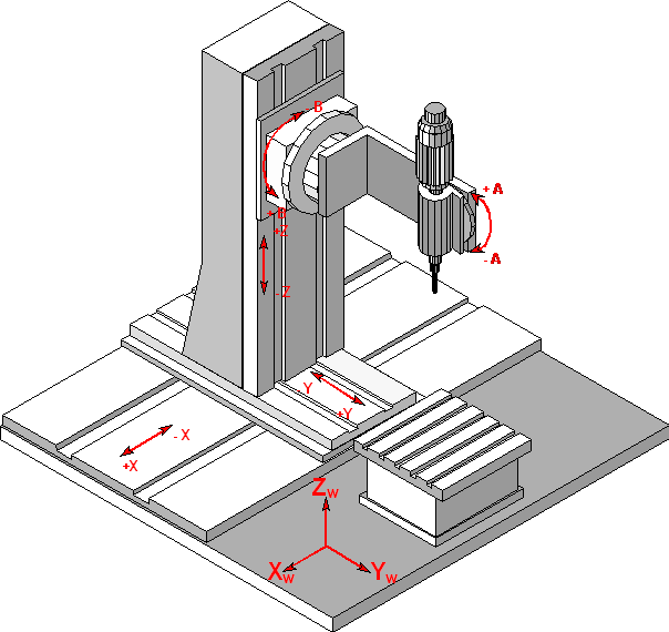
The kinematic structure of this machine consists of three translatory and two rotary axes in tool. This kinematic supports non parallel parallel fixed tool rotation axis B-A to workpiece axes. A virtual axis CV can be used for modification of tool orientation.
Axis configuration in NC channel | ||
Axis designation | X, Y, Z, B, A, CV | |
Axis index | 0, 1, 2, 3, 4, 5 | |
Kinematic structure | ||
| Tool axes | Workpiece axes |
NC axes | X, Y, Z, B, A, CV | - |
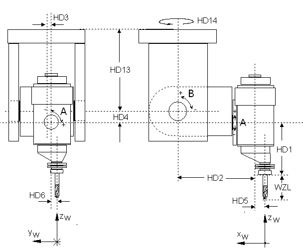
Offset data of kinematic:
HD-Offset | param[i] | Description |
|---|---|---|
HD1 | 0 | Z- Offset to tool fixpoint |
HD2 | 1 | X - Offset |
HD3 | 2 | Y - Offset |
HD4 | 3 | Z - Offset |
HD5 | 4 | X- Offset to tool fixpoint |
HD6 | 5 | Y- Offset to tool fixpoint |
HD7 | 6 | Rotary offset A axis |
HD8 | 7 | Rotary offset B axis |
HD9 | 8 | Rotation sign A axis |
HD10 | 9 | Rotation sign B axis |
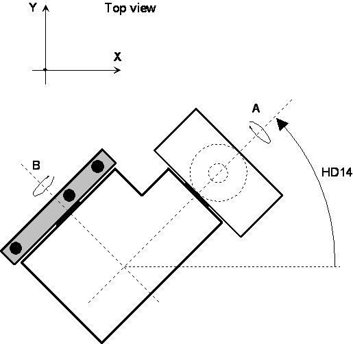
HD14 | 13 | Rotary offset of tool head around Z axis (head position) |
The CV axis is not a physical real existing axis of the kinematic structure. This axis rotates the tool orientation vector around z, this means the angles A and B are calculated depending on the angle of CV.One application can be the perpendicular aligning of one component of tool direction vector depending to programmed contour.For it a simulation axis has to be configured and can be used as usual in NC program.
The permissible ange range of A and B axes is +- 90 degrees.