KIN_TYP_57
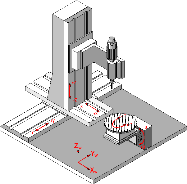
The kinematic structure of this machine consists of three translatory axes in tool and two rotary NC axis in workpiece.
Axis configuration in NC channel | ||
Axis designation | X, Y, Z, B, C | |
Axis index | 0, 1, 2, 3, 4 | |
Kinematic structure | ||
| Tool axes | Workpiece axes |
NC axes | X, Y, Z | B, C |
The machine origin ca be shifted by the parameters HD7..HD9. Differing zero positions of the rotary axes B and C can be adjusted by the parameters HD10 and HD11 in a way, that the internal kinematic model matches to the real machine kinematic. In the same way also differing rotation directions of the B and C axes can be adjusted by the parameters HD12 and HD13. Then, in general in the axes parameters also the signs of commanded and actual values have to be adjusted correspondingly.
Offset data of kinematic:
HD-offset | param[i] | Description |
|---|---|---|
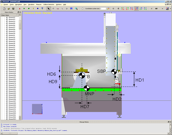
HD1 | 0 | Z tool offset from work holding point to reference point of tool slide SBP |
HD2 | 1 | X axis offset from work holding point to reference point of tool slide SBP |
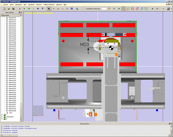
HD3 | 2 | Y axis offset from work holding point to reference point of tool slide SBP |
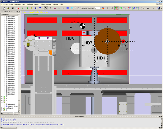
HD4 | 3 | X axis offset from rotation axis B to rotation axis C, origin WCS |
HD5 | 4 | Y axis offset from rotation axis B to rotation axis C, origin WCS |
HD6 | 5 | Z axis offset from rotation axis B to rotation axis C, origin WCS |
HD7 | 6 | X offset from machine origin MNP to rotation axis B |
HD8 | 7 | Y offset from machine origin MNP to rotation axis B |
HD9 | 8 | Z offset from machine origin MNP to rotation axis B |
HD10 | 9 | Rotation offset B axis |
HD11 | 10 | Rotation offset C axis |
HD12 | 11 | Flag of rotation direction B axis |
HD13 | 12 | Flag of rotation direction C axis |